Thermally insulated die plate assembly for underwater pelletizing and the like

a technology of thermal insulation and die plate, which is applied in the direction of auxillary shaping apparatus, ceramic shaping apparatus, manufacturing tools, etc., can solve the problems of large maintenance and fragile plate assembly, and achieve the effect of improving thermal insulation in operation and strength and robustness

Inactive Publication Date: 2010-02-18
GALA INDUSTRIES INC
View PDF40 Cites 9 Cited by
  • Summary
  • Abstract
  • Description
  • Claims
  • Application Information

AI Technical Summary

Benefits of technology

[0030]Still another object of the present invention is to provide a thermally insulated die plate assembly in accordance with the two preceding object in which the raised ridge has a trapezoidal shape in vertical cross-section to aid in channeling heat to the orifice protrusions and thus maintain the process melt at a desired temperature in the extrusion orifice at the die face.
[0036]A final object to be set forth herein is to provide a thermally insulated die plate assembly which will conform to conventional forms of manufacture, will have improved strength and robustness, will maintain the insulating air pocket tightly sealed to provide improved thermal insulation in operation, and will be economically feasible, long-lasting and relatively trouble-free in use.

Problems solved by technology

This die plate assembly is very fragile and highly susceptible to process melt leakage, thus requiring considerable maintenance.

Method used


Image

  • Thermally insulated die plate assembly for underwater pelletizing and the like
  • Thermally insulated die plate assembly for underwater pelletizing and the like
  • Thermally insulated die plate assembly for underwater pelletizing and the like

Examples


second embodiment

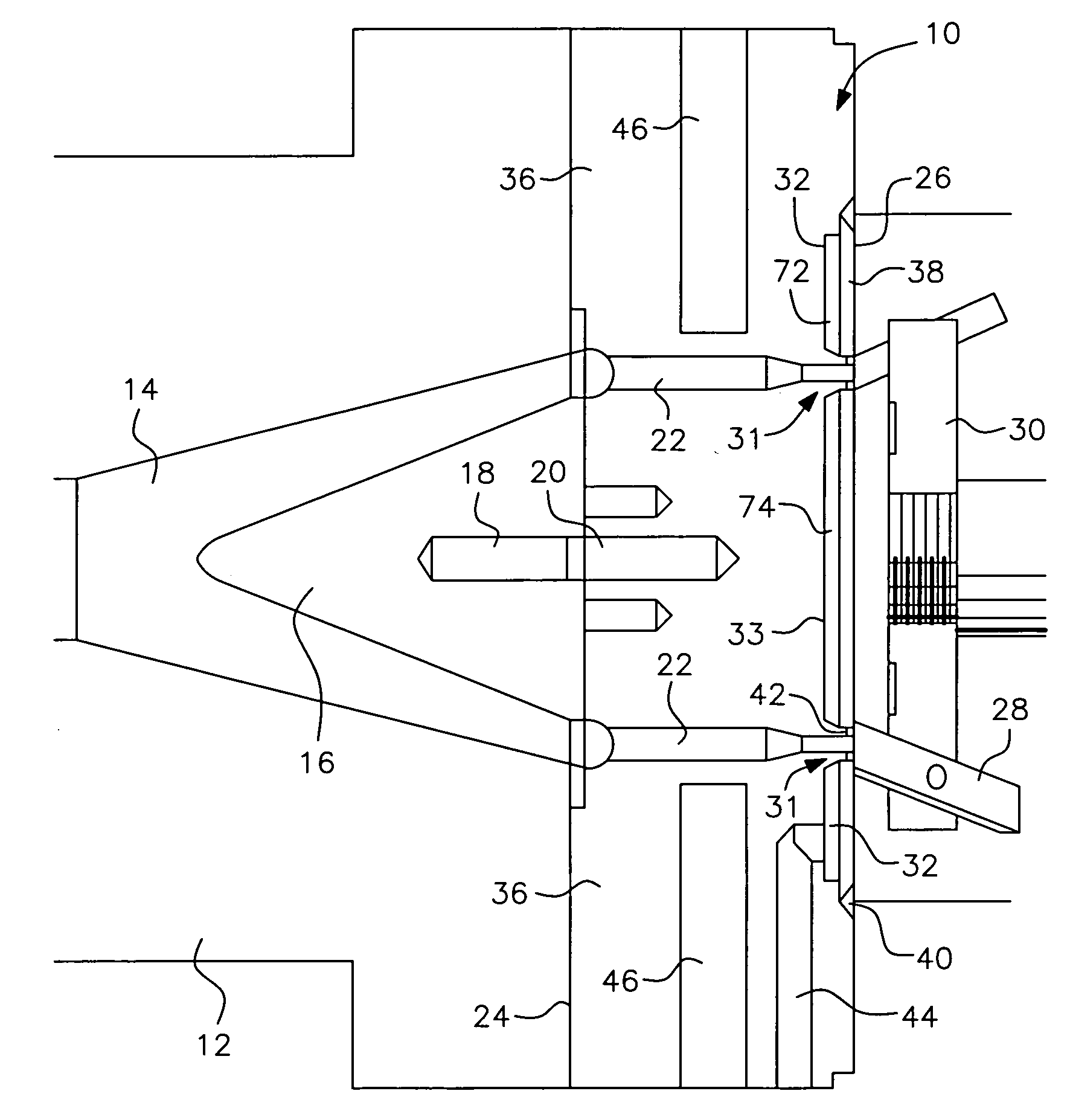
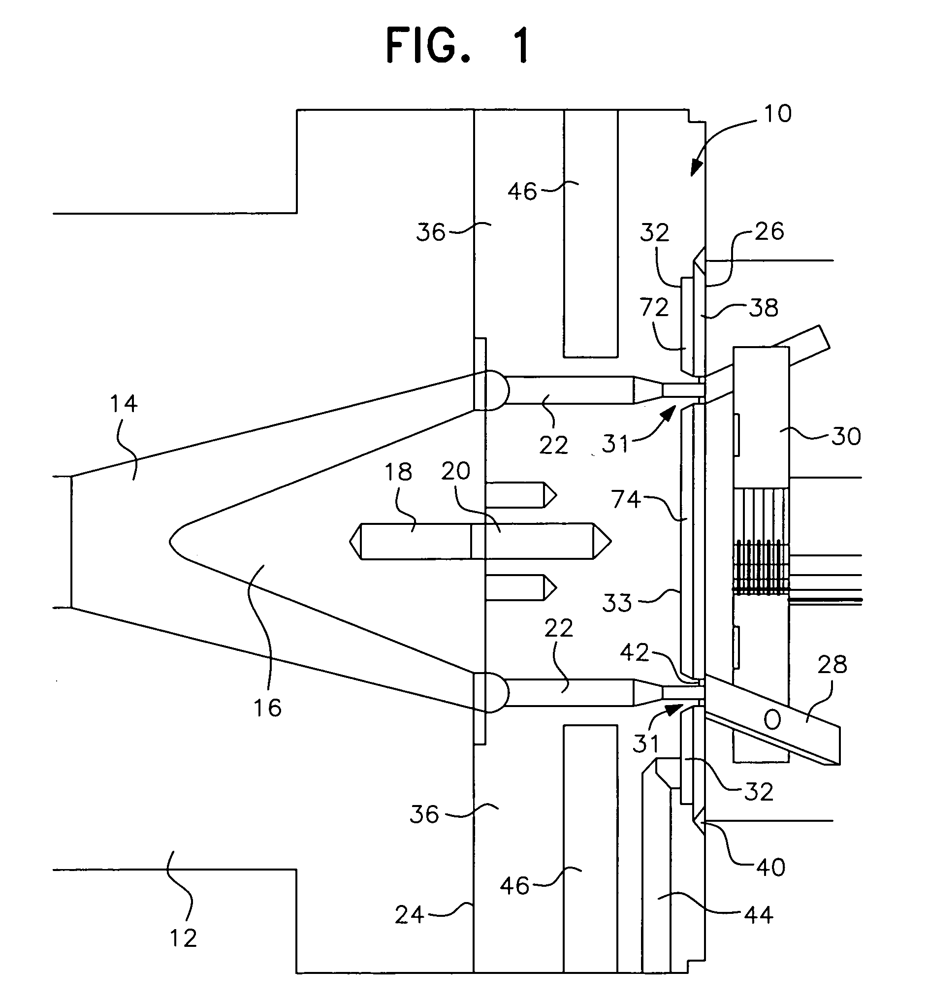
[0062]Turning to FIGS. 4 through 9 there is shown a two-piece die plate assembly, generally designated by reference numeral 100, in accordance with the present invention. The die plate assembly 100 includes a die plate outer ring 105 and removable center die insert 106. Since many of the components of the die plate assembly 100 are the same as or very similar to the components of the die plate assembly 10, the same reference numerals are carried forward from the latter for corresponding components in the former, but preceded by the “1” digit.

[0063]Similarly to the FIG. 1 embodiment, the die plate assembly 100 is attachedly connected to an inlet housing 112 from a melting and / or mixing apparatus (not shown). The inlet housing 112 includes a passageway 114 for process melt as heretofore described. Nose cone 116 directs the process melt to the upstream side 124 of the removable insert 106 to which it is attachedly connected by threaded rod (not shown). The threaded rod is screw threade...

first embodiment

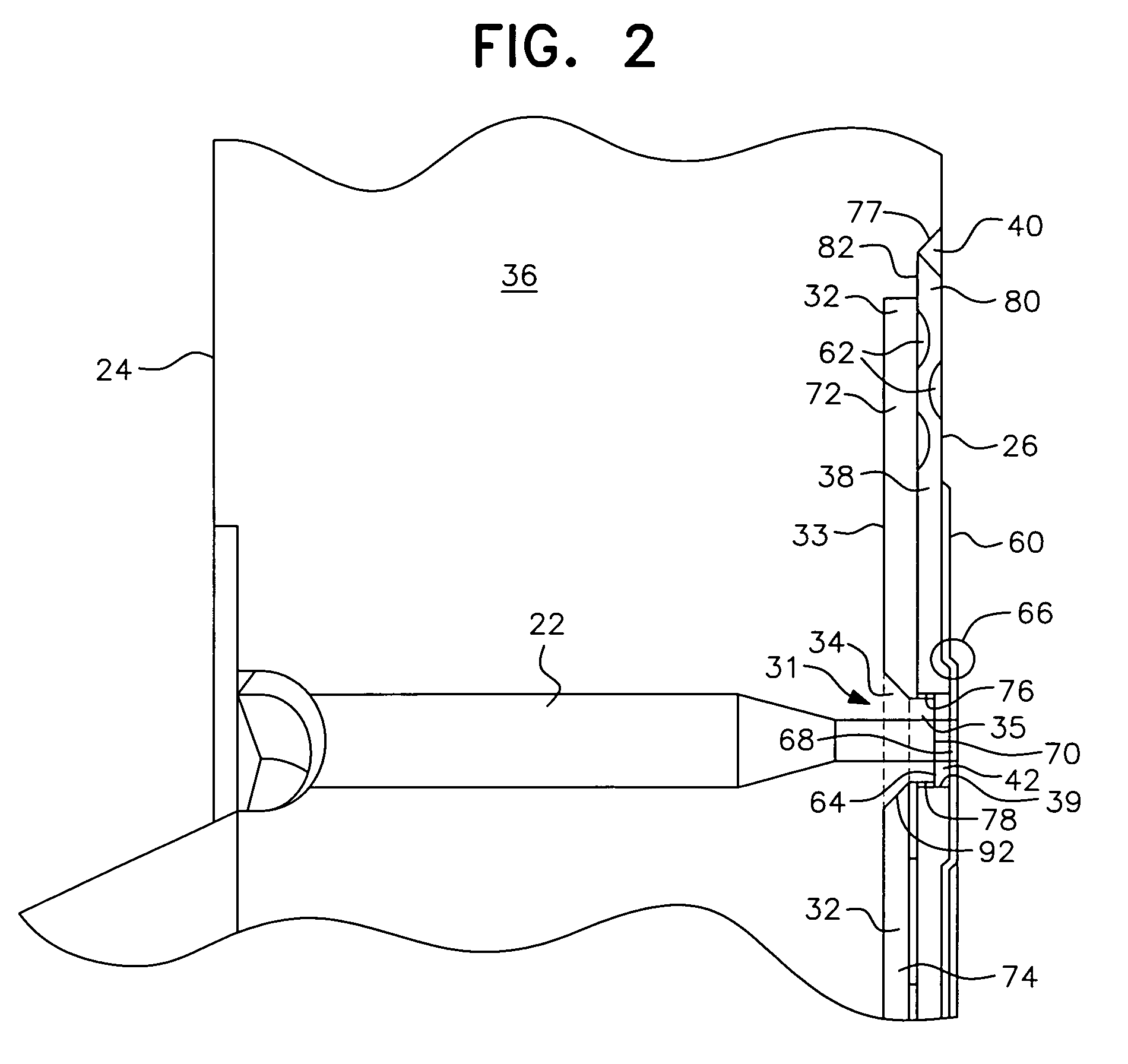
[0065]The central areas of the downstream face 126 of insert 106 are machined or cut out to provide a central circular recess or cavity 133 in the same manner as described above for the first embodiment, including raised circular ridge 134 and orifice protrusions 135, which together define the extrusion orifice extensions 131 and encase the extrusion orifices 122 through the cavity 133. A circular cover plate 138 with holes 139 matching the distal ends 170 of the orifice protrusions 135 overlays the recess cavity 133 to form a thin, continuous thermal air pocket or air chamber 132 across the insert 106 generally parallel to the die face 126. The upstream side of cover plate 138 is also provided with a generally circular counterbore 176 which includes the outlet holes 139 and conforms to and receives the circular array of orifice protrusions 135. The extrusion orifice extensions 131 made up of the raised circular ridge 134 and orifice protrusions 135 serve to channel and provide heat...


PUM

PropertyMeasurementUnit
depthaaaaaaaaaa
depthaaaaaaaaaa
temperatureaaaaaaaaaa

Abstract

An insulated die plate assembly for use in underwater pelletizing and other granulation processes includes a thin, continuous air chamber formed across the plate assembly generally parallel to the die face such that the heated upstream portion of the die plate assembly is thermally insulated from the downstream portion. The air chamber is atmospherically equilibrated by venting the air chamber to the atmosphere. The plurality of extrusion orifices, either individually or in groups, are formed in extrusion orifice extensions that extend through the insulation chamber so that the process melt to be granulated can pass therethrough. The orifice extensions and the components forming the air chamber around the orifice extensions are specially configured to channel heat along said extensions to maintain the process melt therein at a desired temperature, to help rigidify the die plate assembly and to better seal the air chamber.

Description

FIELD OF THE INVENTION[0001]The present invention generally relates to an insulated die plate assembly for use in underwater pelletizers and other granulation processes that include hot-face or non-fluidic pelletization. More specifically, the present invention relates to an insulated die plate assembly that includes a thin continuous air pocket or chamber formed across the plate assembly such that the upstream portion of the die plate assembly is thermally insulated from the downstream portion of the same assembly, thus allowing the respective portions to co-exist at different temperatures. The plurality of extrusion orifices, individually or in groups, extend through extrusion orifice extensions that project through the insulation air pocket or chamber so that the material to be pelletized or granulated can pass therethrough.BACKGROUND OF THE INVENTION AND PRIOR ART[0002]Underwater pelletization equipment and its use following extrusion processing have been implemented for many ye...

Claims


Application Information

Patent Timeline
Patent Type & Authority Applications(United States)
IPC IPC(8): B29B9/00B29C48/04B29C48/05B29C48/12B29C48/30B29C48/345
CPCB29B9/065B29B9/06B29C2793/0027B29C48/865B29C48/05B29C48/0022B29C48/345B29C48/911B29C48/04B29C48/12B29B7/582B29B7/826B29C48/30B29B9/02
Inventor FRIDLEY, MICHAEL A.
Owner GALA INDUSTRIES INC
Why Eureka
Try Eureka