Method and device for pin removal in a confined space

a technology of confined space and controlled mechanical removal, which is applied in the direction of mechanical equipment, machines/engines, manufacturing tools, etc., can solve the problems of difficult, time-consuming, and costly, and the space for accessing particular machine parts such as pins with such tools is confined, and maintenance often requires difficult manual labor and individual handling of maintenance operations. , to achieve the effect of less cost and less tim

Inactive Publication Date: 2010-02-18
GENERAL ELECTRIC TECH GMBH
View PDF23 Cites 3 Cited by
  • Summary
  • Abstract
  • Description
  • Claims
  • Application Information

AI Technical Summary

Benefits of technology

[0012]It is an object of the invention to provide a method and means to remove pins that are accessible only from a constricted space. Additionally, the material surrounding the pin to be removed is to remain undamaged. Compared to methods of the state of the art, the method shall be performed either on a machine “on-site” or in a classical workshop operation in less time and at less cost. It shall be applicable to the removal of pins in any machine, in particular turbines.
[0017]In order to increase the efficiency of the cutting or drilling, an abrasive material is added to the flow of water within the water jet tool, such as for example garnet or “sand-like” substances.
[0020]A water jet used to perform the method according to the invention comprises a nozzle having a longitudinal axis that is angled with respect to the longitudinal axis of the tool main body. The overall length of the water jet tool in line with the water jet directed onto the pin to be removed is thereby reduced in comparison to water jet tools of the state of the art. This facilitates access within a constricted space.
[0022]A further embodiment of the water jet tool according to the invention comprises a supply line for abrasive material connected to the water line within the tool that is connected to the water flow within the tool following the angle between the main and the nozzle. This facilitates a design of the angled portion independent of the abrasive, i.e. that withstands the pressure of the water alone.
[0023]The method according to the invention allows an “in-situ” removal of a pin in constricted space facilitated by the angled water jet tool nozzle. Compared to water jet tools of the state of the art, it has a reduced overall length in line with the water jet impinging onto the pin to be removed. This allows its application in much smaller access spaces. Transport and segmentation of the surrounding material or machine is no longer necessary in order to enlarge the access space. The method furthermore allows removal of pins with minimal damage to the surrounding material. Problems associated with EDM are entirely avoided. The material removal method is also performed within a significantly shorter time span compared to the mentioned methods of the state of the art.

Problems solved by technology

Such removal is in many circumstances difficult, time consuming, and costly.
For the maintenance of machines, such as motors and turbines, the space for access to particular machine parts such as pins with such tools is confined.
The maintenance frequently requires difficult manual labor and individual handling of maintenance operations within the given confined space.
Either method of maintenance is costly not only due to its labor intensity but also due to the long downtime of the machine being out of operation.
However, this is a difficult procedure because the space between the blade rows is confined, in some cases as narrow as ten centimeters.
Both methods, rotor segmentation and “in situ” removal, are time-consuming and costly procedures.
The water jet apparatus comprises an extensive assembly of large size and thus unsuitable for drilling in a confined space.

Method used


Image

  • Method and device for pin removal in a confined space
  • Method and device for pin removal in a confined space
  • Method and device for pin removal in a confined space

Examples


Embodiment Construction

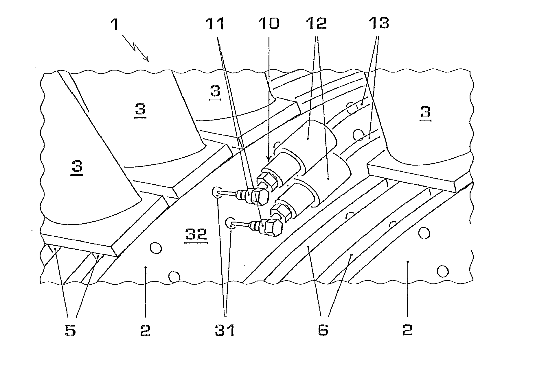
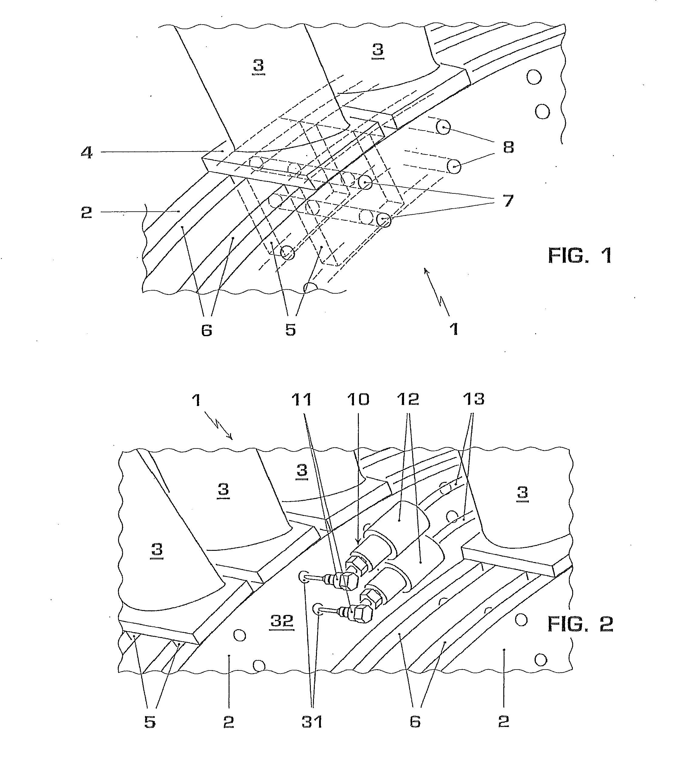
[0031]Blades are secured in blade rows to a steam turbine rotor by various means. FIG. 1 shows a portion of a steam turbine rotor 1, on which blade rows are secured by means of a turbine rotor wheel 2. Each blade 3 is equipped with a blade platform 4 and a two-part blade root 5. Each of the radially extending parts of the root 5 is placed in a circumferential groove 6 in the turbine wheel 2. In order to secure each blade root to the turbine wheel 2, one or more pins 7 are placed in bores 8 extending through the turbine wheel 2 and the blade root 5. The pins are placed in the bores by a high-tension press-fit.

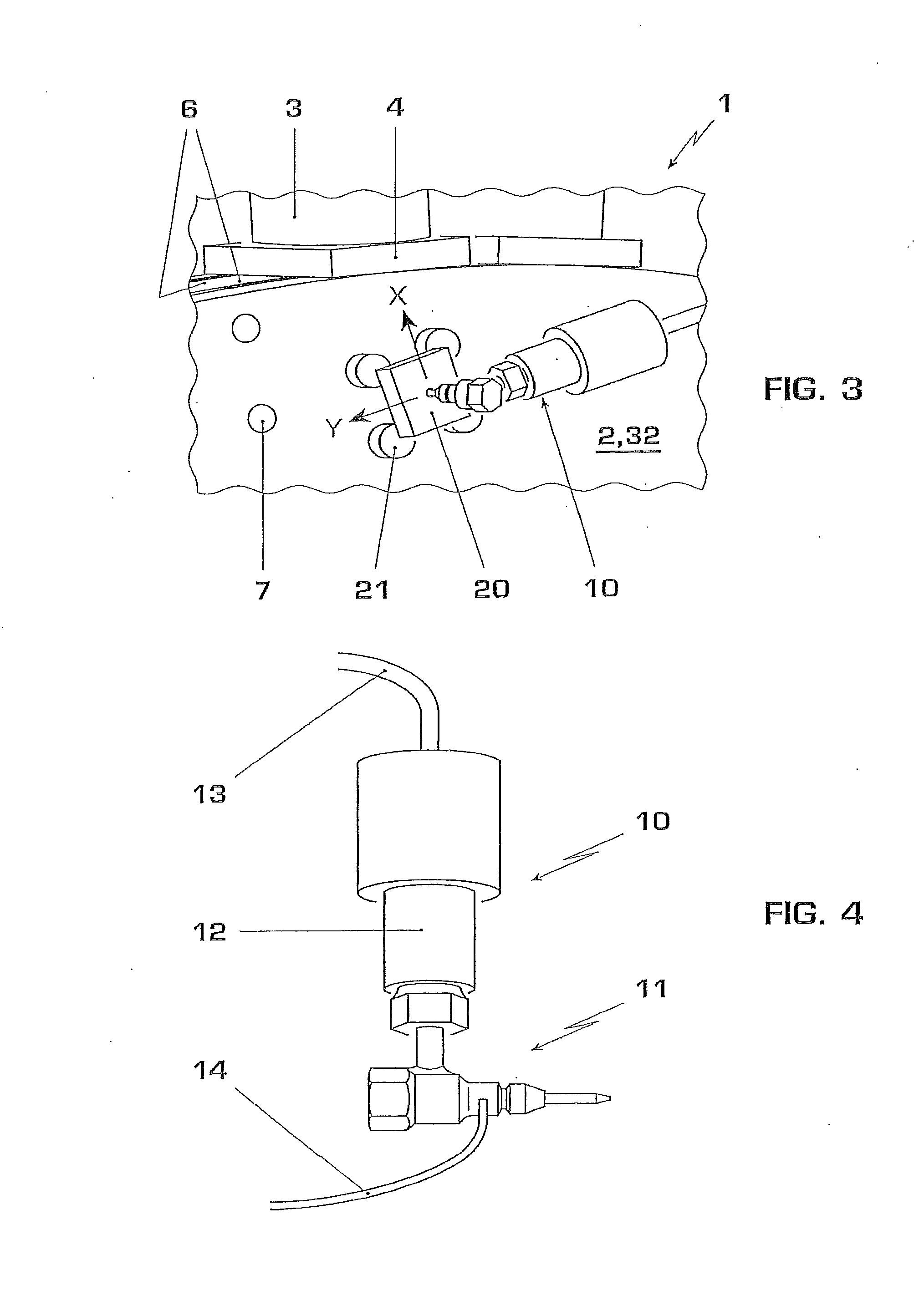
[0032]When the turbine is due for service maintenance and blading replacement, the blades must be removed. FIG. 2 shows two turbine wheels 2, with blade rows 3 secured to them by their roots 5 in grooves 6. The space between the blade rows is confined so that a conventional tool cannot be directed straight at a pin or does not fit at all. According to the invention, the press-fi...


PUM


Abstract

A method for drilling or cutting a pin surrounded by solid material includes the use of a water jet tool having a nozzle that is arranged at an angle with respect to a main body of the water jet tool. The water jet is directed over a portion of the surface of the pin, and removes that portion thereby fragmenting the pin. In order to minimise damage to the surrounding material, the portions removed touches the interface between the pin and the surrounding solid material at a minimal number of points and over a minimal extent of the interface. The method is applicable in particular to the removal of pins used in a press-fit for the securing of blades on a turbine rotor. The method facilitates “in situ” removal of pins within a confined space in a short time and at reduced cost.

Description

CROSS-REFERENCE TO RELATED APPLICATIONS[0001]This application is a continuation of U.S. application Ser. No. 11 / 958,569 filed on Dec. 18, 2007, which claims priority to European Application No. 07100237.2 filed on Jan. 8, 2007, the entire contents of which are incorporated herein by reference.TECHNICAL FIELD[0002]The invention pertains to a method and device for the controlled mechanical removal of pins in a confined access space. It pertains in particular, but not exclusively, to the removal of press-fit pins in steam turbine blading.BACKGROUND ART[0003]Mechanical removal of pins in a confined space for access is typically performed by means of hand drills or other cutting machinery such as mills. Such removal is in many circumstances difficult, time consuming, and costly.[0004]For the maintenance of machines, such as motors and turbines, the space for access to particular machine parts such as pins with such tools is confined. The maintenance frequently requires difficult manual l...

Claims


Application Information

Patent Timeline
Patent Type & Authority Applications(United States)
IPC IPC(8): B24C3/00
CPCB23P6/002B24C1/045F01D5/3053F01D5/005B26F3/004Y10T83/364Y10T83/0591
Inventor MOSER, ROLANDHULME, CHRISTOPHER JOHN
Owner GENERAL ELECTRIC TECH GMBH
Why Eureka
Try Eureka