
Inflatable chamber device for motion through a passage

a technology of inflatable chambers and passages, which is applied in the field of inflatable chamber devices, can solve the problems of slow and monotonous outflow of fluid into the next chamber in the series, increased inflation rate and propulsion speed, so as to achieve increased inflation rate and propulsion rate, the effect of increasing inflation rate and increasing propulsion ra

Active Publication Date: 2010-02-18
TECHNION RES & DEV FOUND LTD
View PDF11 Cites 31 Cited by
  • Summary
  • Abstract
  • Description
  • Claims
  • Application Information

AI Technical Summary

Benefits of technology

[0012]The device is operable with a series of only two inflatable chambers, each of which expands radially and axially when inflated, but the use of more than two chambers may have an advantage in that the radial pressure on the walls is spread out over more chambers, thus reducing the internal pressure required to anchor the relevant chambers of the device. Furthermore, the use of a larger number of chambers may enable larger payloads to be transported or pulled by the device.
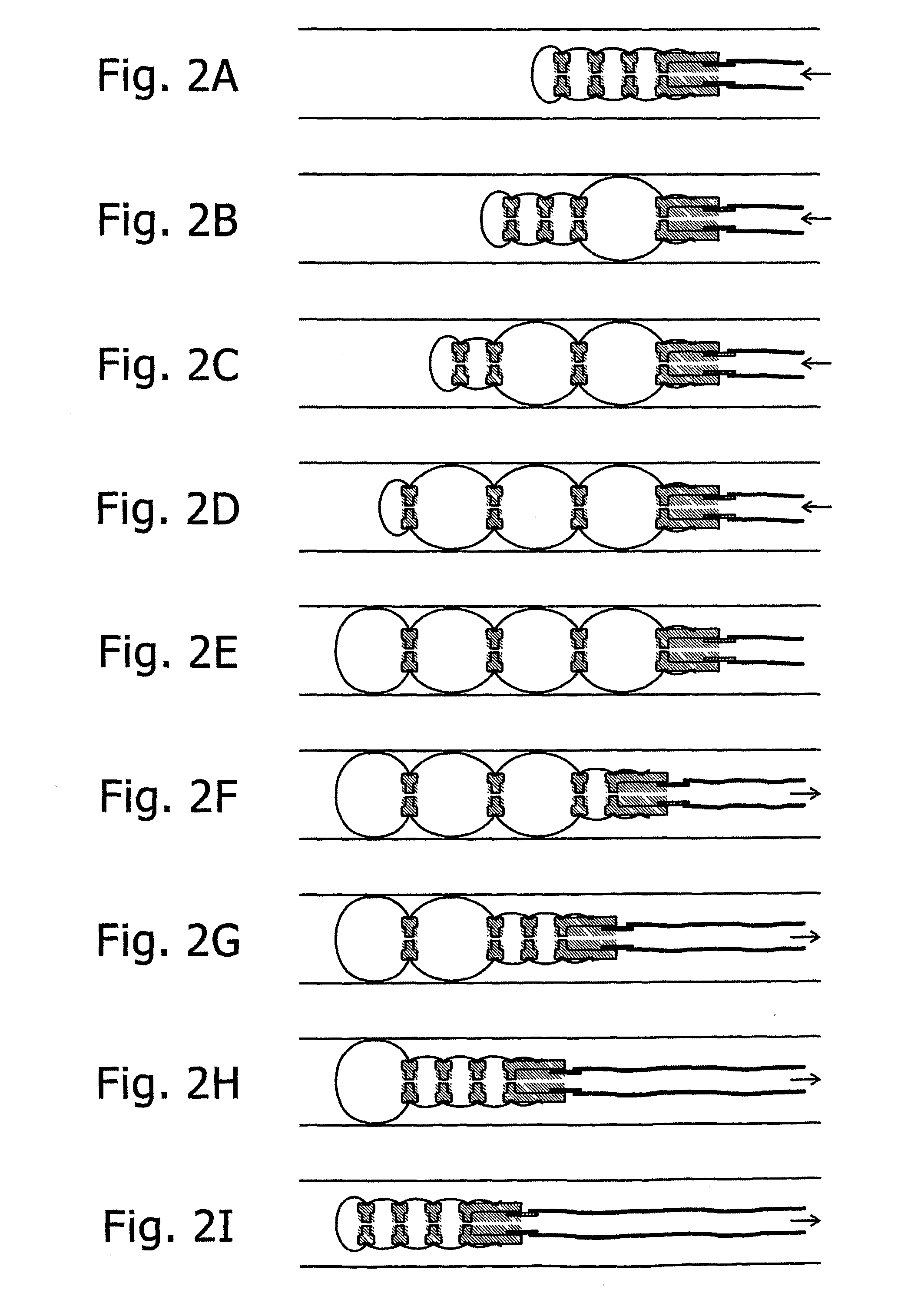
[0014]This combination of events thus enables each chamber in the series to inflate and anchor at a faster rate than the inflation rate of the immediately succeeding chamber. This feature enables the present invention to overcome a possible operative difficulty of prior art, single feed, sequentially inflatable chamber locomotion devices, in that it is difficult to obtain the optimum conditions to combine rapid propulsion speed with sequential inflation of the series of chambers. In such devices, if the orifices between chambers are too small, the inflation rate and propulsion speed are too low. If the orifices between chambers are too large, the chambers inflate so rapidly that there is a tendency for the inflation to approach simultaneous filling conditions, and earlier chambers anchor onto the inside walls of the lumen before they have fully expanded axially, such that the increased inflation rate is not translated into an increased propulsion rate. The use of the non-monotonous elastic material characteristic, according to the present invention, overcomes this possible problem by enabling the use of comparatively large connecting orifices between chambers so that inflation occurs rapidly, but at the same time, introducing a delay in the inflation of the subsequent chambers, such that a subsequent chamber does not inflate significantly until the previous chamber is properly anchored in the lumen. This provides the desired combination of orderly and rapid inflation and anchoring with a high propulsion speed.

Problems solved by technology

Consequently, the outflow of fluid into the next chamber in the series is also slow and monotonous.
In such devices, if the orifices between chambers are too small, the inflation rate and propulsion speed are too low.
If the orifices between chambers are too large, the chambers inflate so rapidly that there is a tendency for the inflation to approach simultaneous filling conditions, and earlier chambers anchor onto the inside walls of the lumen before they have fully expanded axially, such that the increased inflation rate is not translated into an increased propulsion rate.

Method used


Image

  • Inflatable chamber device for motion through a passage
  • Inflatable chamber device for motion through a passage
  • Inflatable chamber device for motion through a passage

Examples


Embodiment Construction

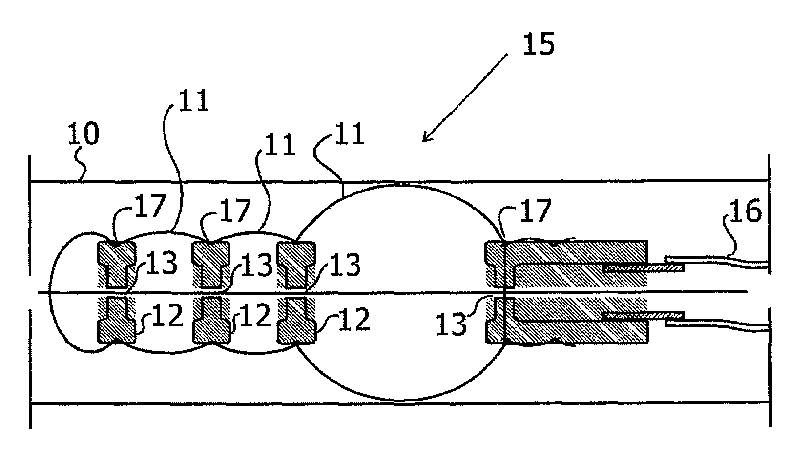
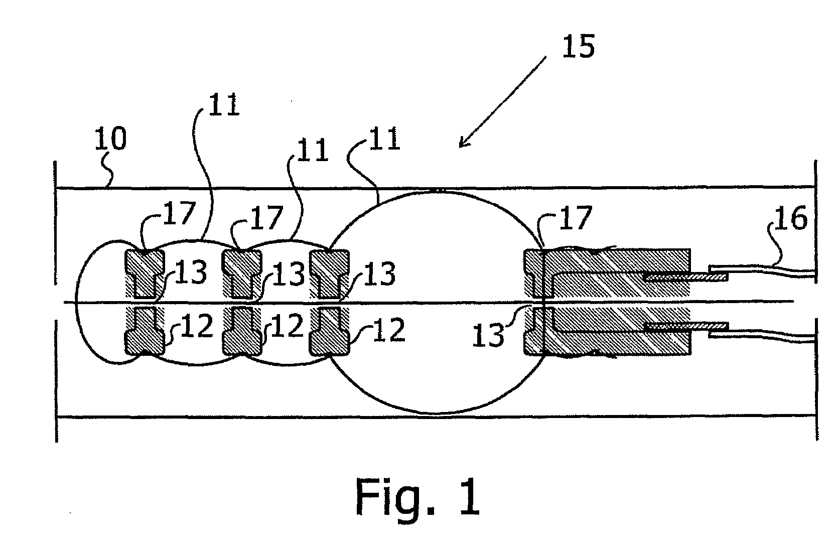
[0038]Reference is now made to FIG. 1, which illustrates schematically a tip-propelled catheter device 15 for traveling down a lumen 10, as is known in the art. The device may preferably comprise a number of balloons 11 connected to each other by separators 12 with one or more small openings, preferably in the form of orifices 13 formed therein, such that all the balloons comprise a single volume, inflatable through a single input. For ease of construction, the device can alternatively and preferably comprise a single inflatable balloon divided into separate balloon segments by separators with orifices such that the entire segmented balloon can be inflated through a single input. The balloon fabric is preferably held in place relative to the separators 12 by means of rings 17 or glued or molded to the separators. Whichever preferred construction is used, the device is connected by a single tube 16 to a fluid supply for inflating the balloons or the balloon segments. For the sake of ...


PUM


Abstract

A self-propelled device for locomotion through a lumen, comprising a set of serially arranged inflatable chambers, adjacent chambers being fluidly connected, and a fluid source attached to one end of the set, such that the chambers inflate sequentially. The chambers are constructed of an elastic material and have a wall thickness and dimensions such that they have a characteristic with a non-monotonous relationship between the inflation pressure within the chamber and the chamber's inflated size. The characteristic is such that after an initial inflation pressure peak, the non-monotonous relationship adopts a negative slope, such that the volume of the chamber increases more rapidly than the volume of fluid flowing into it, and the inflation pressure of the chamber falls. This effect causes the chamber to inflate and anchor rapidly, while essentially slowing down the inflation of the succeeding chamber until inflation of the first is complete.

Description

FIELD OF THE INVENTION[0001]The present invention relates to the field of inflatable chamber devices capable of self propelled motion through tubes, especially for endoscopic and vascular use.BACKGROUND OF THE INVENTION[0002]The ability to crawl through long, flexible, and curved tubes has long been a challenge for engineers since numerous applications can benefit from a reliable solution. This ranges from medical applications for treatment and diagnosis to sewer pipes, gas pipes and power plants.[0003]Current solutions often contain a payload such as a camera, which is pushed from the back by a long flexible rod or wire. This is the solution currently used in many medical applications with guide wires or catheters to deliver diagnosis or treatment instruments to the desired position, e.g. in catheterization, colonoscopy, ureteroscopy, dilating balloon, and others.[0004]In some type of applications, it is impossible to push the active head from the back because the force required wo...

Claims


Application Information

Patent Timeline
Patent Type & Authority Applications(United States)
IPC IPC(8): A61B1/01A61F2/958
CPCA61B1/00082A61B1/00156A61B1/31A61B17/12045A61B17/12136F16L55/44A61M25/10A61M2025/1059F16L55/30F16L55/34F16L55/36A61M25/0105A61M25/0116A61M25/0155
Inventor GLOZMAN, DANIELHASSIDOV, NOAMSHOHAM, MOSHE
Owner TECHNION RES & DEV FOUND LTD
Learn More