
Internet video receiver

a receiver and video technology, applied in the field of internet video receivers, can solve the problem of limited access to certain approved suppliers/servers, and achieve the effect of facilitating the delivery of television

Inactive Publication Date: 2010-02-18
SEN SHONDIP +2
View PDF9 Cites 42 Cited by
  • Summary
  • Abstract
  • Description
  • Claims
  • Application Information

AI Technical Summary

Benefits of technology

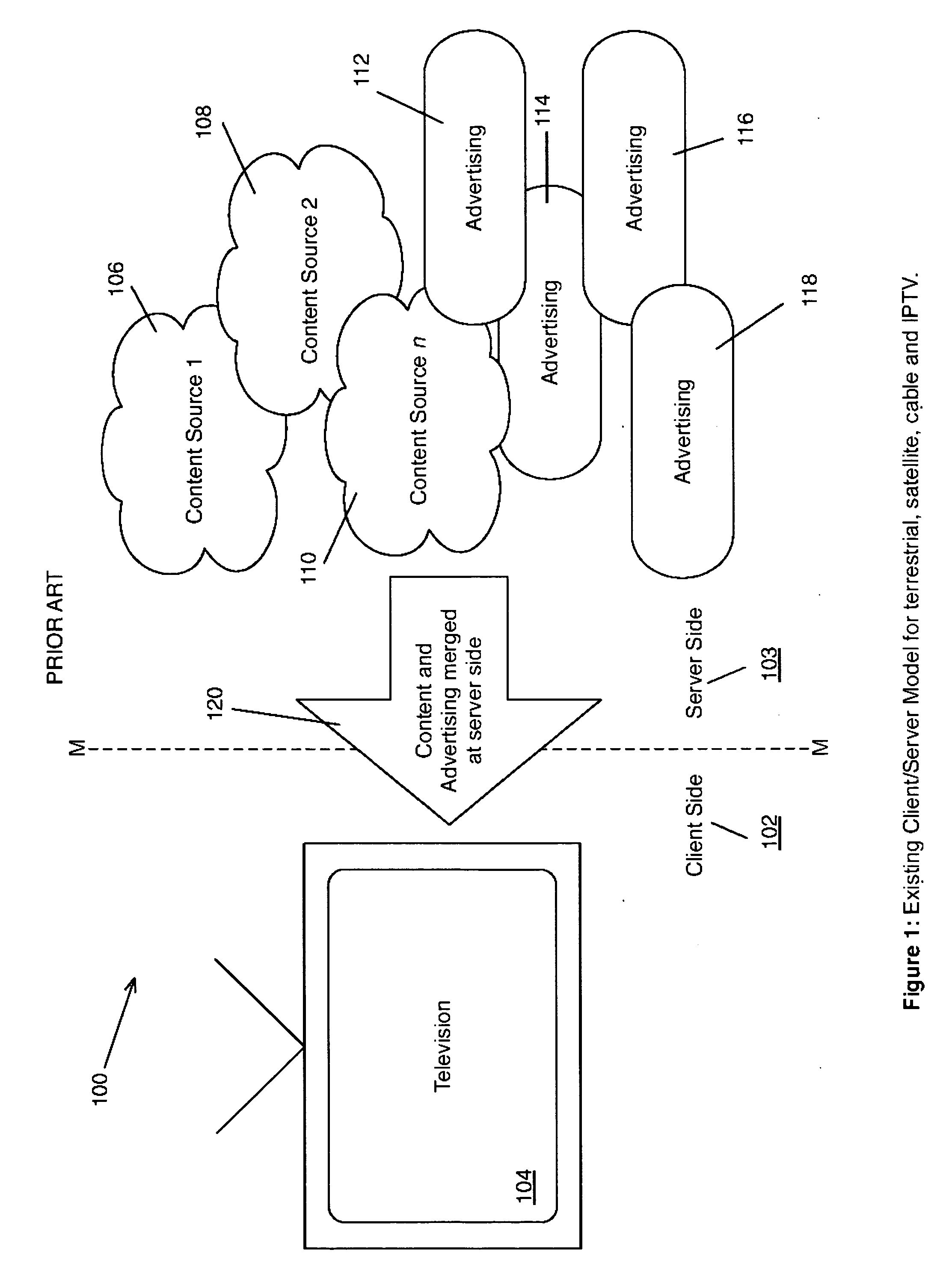
[0016]Historically, television has been a one-way communication medium with a single broadcaster transmitting content and advertising to many receivers. Different technologies have facilitated the delivery of television through terrestrial broadcasting, satellite, cable and Internet Protocol Television (IPTV). Some of these t...

Problems solved by technology

The problem with the existing approach is that the overlays are determined by a single content creator / provider / broadcaster at the server side.
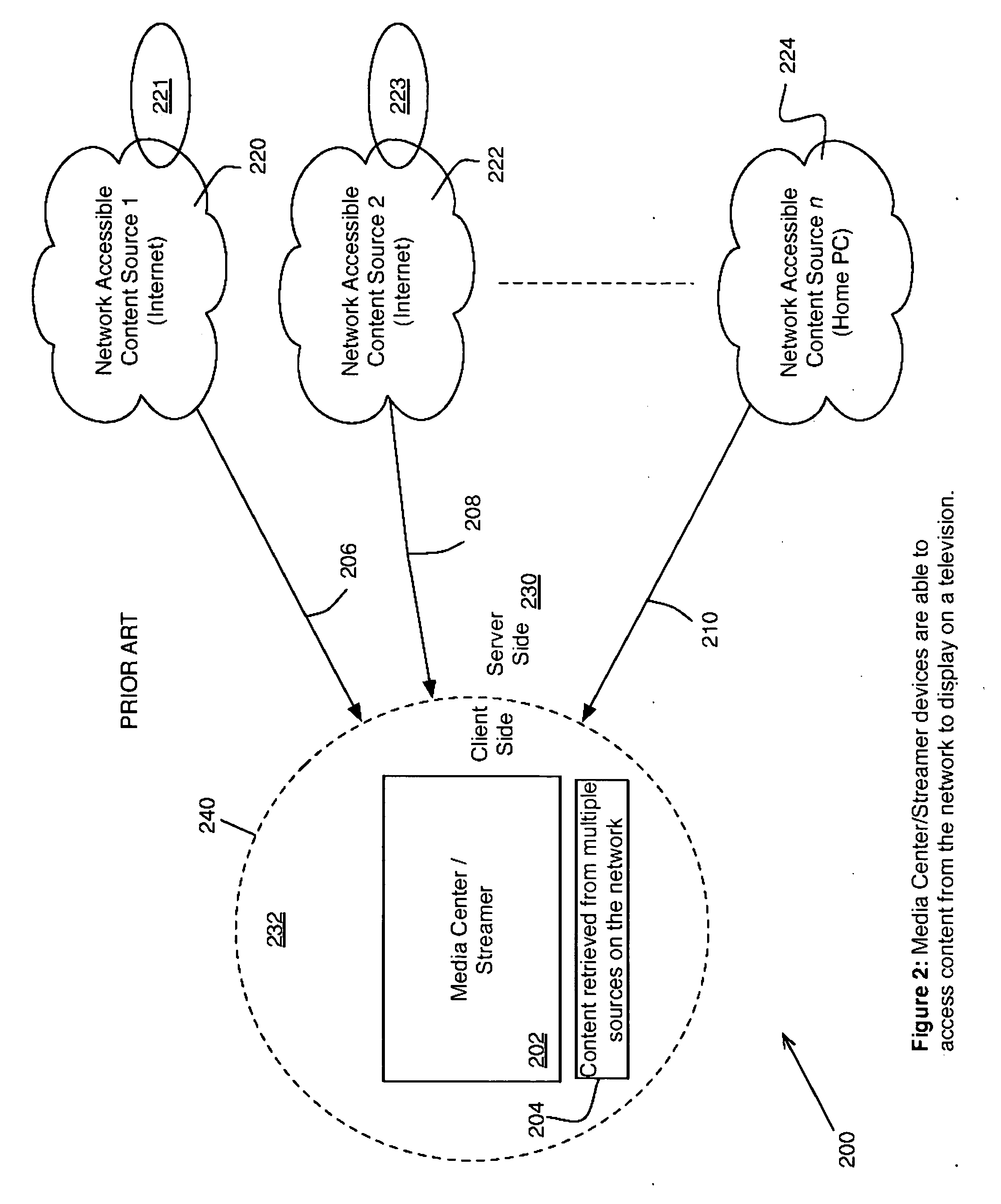
One disadvantage of existing methods like these for delivering content to a television is that access is limited to only certain approved suppliers / servers because of the closed nature of the media center 202 and therefore the delivery medium.

Method used


Image

  • Internet video receiver
  • Internet video receiver
  • Internet video receiver

Examples


embodiment examples

IVR Embodiment Examples

Embodiment 1

[0204]Packaged in a Secure Digital (SD) memory card. The IVR has the physical appearance, mechanical properties and external digital interface of an SD memory card. The IVR can be used with any host device that is able to read an SD memory card. Examples of host devices are televisions, DVD players, cell / mobile / smart phones, MP3 players, media players, laptop computers, desktop computers and other personal entertainment devices that are able to play content from an SD memory card.

[0205]The IVR presents the Virtual File system (VFS) in a suitable format (for example Microsoft FAT) to the host playback device via the digital interface. To the host device it appears as if the WR is an ordinary SD memory card storing media content.

[0206]This embodiment of the IVR may also implement the Secure Digital Input Output (SDIO) protocol to communicate with the host device.

[0207]This embodiment has the properties of Form Factor 1 and is represented in FIG. 6.

embodiment 2

[0208]With a Universal Serial Bus (USB) connector the IVR can be used with any host device that is able to read from a USB mass storage device. Examples of host devices are televisions, DVD players, laptop computers, desktop computers and other personal entertainment devices that are able to play content from a USB mass storage device.

[0209]The IVR presents the Virtual File system (VFS) in a suitable format (for example Microsoft FAT) to the host playback device via the digital interface. To the host device it appears as if the IVR is an ordinary USB mass storage device storing media content.

[0210]The physical appearance of this embodiment is similar to a USB key / thumb drive where the whole IVR is plugged into a USB socket. This embodiment can also be packaged in a larger casing where an extension cable is used to connect the IVR to the USB port on the host device.

[0211]This embodiment has the properties of Form Factor 1 and is represented in FIG. 6.

embodiment 3

[0212]A set-top-box. The IVR provides functionality in a self-contained separate unit. The IVR has a codec to decompress the content into a signal that can be received by a television. The IVR is connected to the television through an audiovisual interconnect such as analog composite, digital HDMI or similar.

[0213]It is the task of the IVR to provide a suitable user interface and controls for navigating the VFS and to control playback.

[0214]This embodiment has the properties of Form Factor 2 and is represented in FIG. 7.


PUM


Abstract

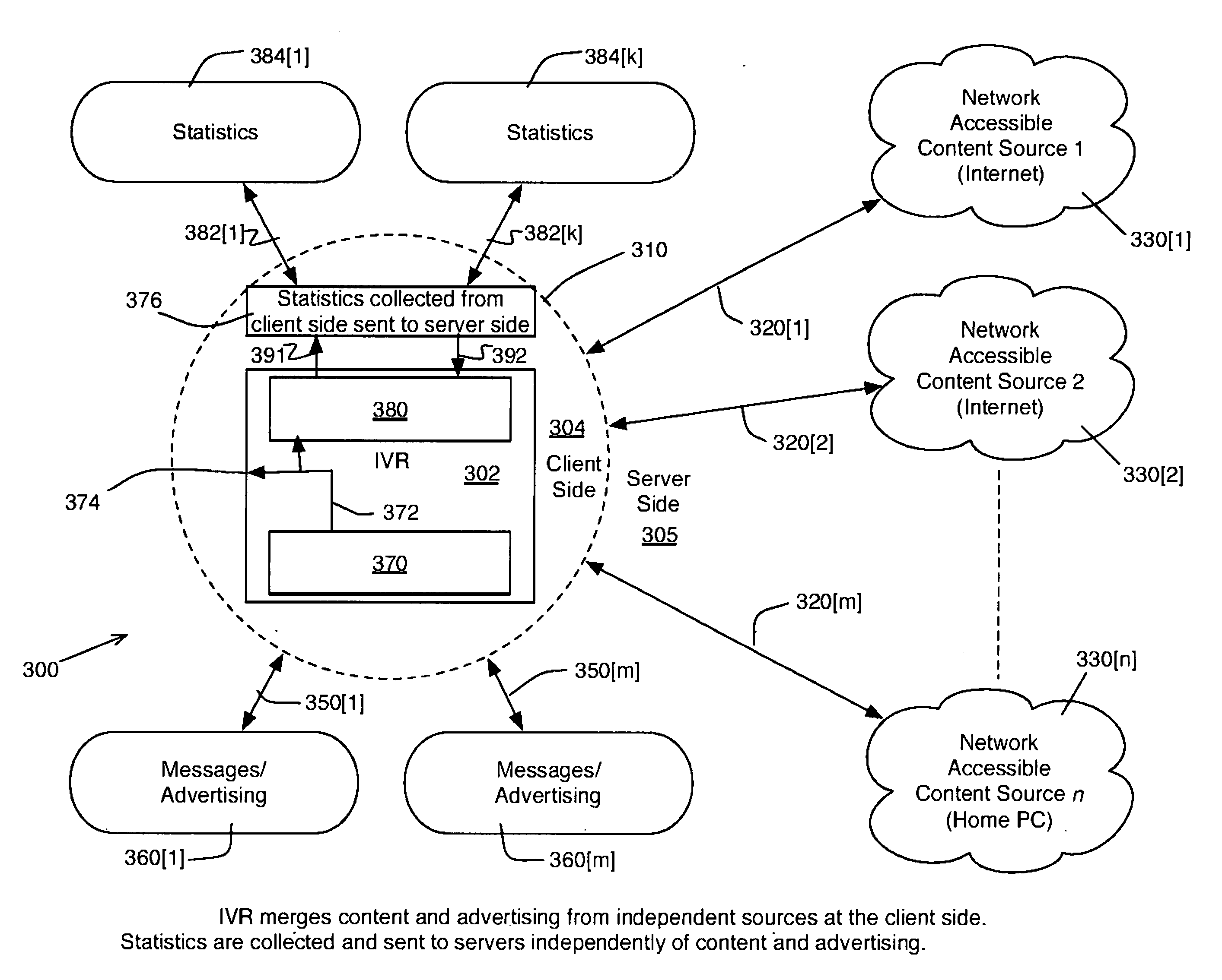
An Internet Video Receiver (IVR) is an appliance for delivering content from the Internet for viewing on a television screen or other device. The major contribution that we have made is to shift the position where advertising is merged with content in the delivery of television services. Previously, content was delivered by a single service provider through a closed medium to many clients. The content and advertising was preselected by the service provider at the server side and delivered to the television on the client side with limited customization for individual viewers. With an IVR, the user can choose content from many independent suppliers from the Internet which is merged with independently supplied advertising in the IVR at the client side. Merging content with advertising in the IVR at the client side provides a new method for delivering a customized television service that can be tailored to individual viewers. Statistical information about content that has been viewed using the IVR is collected at the client side and is sent to destinations on the server side independently of the content and / or advertising suppliers. All information crossing the client / server boundary between the IVR on the client side and independent services on the server side in either direction are transactions for which a fee can be charged.

Description

REFERENCES CITED [0001]U.S. Patent Documents4,887,204December 1989Johnson et al.364 / 200; 364 / 283.1; 364 / 228.3;364243414,907,086March 1990Truong358 / 183; 340 / 734; 340 / 7915,313,646May 1994Hendricks et al.395 / 600; 395 / 435; 395 / 160; 364DIG1;36422281; 364 / 282.1; 364 / 283.1;364 / 2865,491,517February 1996Kreitman et al.348 / 581; 348 / 586; 348 / 599; 348 / 7225,603,019February 1997Kish395 / 621; 395 / 413; 395 / 444; 395 / 481;39520012; 364 / 256.3; 364 / 962;364DIG1; 364DIG26,078,328June 2000Schumann et al.345 / 4186,195,692February 2001Hsu709 / 219; 345 / 327; 348 / 906; 348 / 5656,573,945June 2003Wu et al.348 / 584; 348 / 581; 348 / 587; 348 / 588;348 / 589; 345 / 6412007 / 0130601June 2007Li et al.725112000; 7251130007,017,175Mar. 21, 2006Alao, et al.725 / 105; 348 / E7.054; 348 / E7.07;709 / 203; 725 / 10920020087402Jul. 4, 2002Zustak, Fred J.; et al.705 / 14; 705 / 2620020124249Sep. 5, 2002Shintani, Peter Rae; et al.725 / 32; 348 / E7.075; 386 / E5.001;725 / 105; 725 / 13120040163101Aug. 19, 2004Swix, Scott R.; et al.725 / 9; 348 / E7.075; 705 / 10; 725 / 35;7...

Claims


Application Information

Patent Timeline
IPC IPC(8): H04N7/173
CPCH04N7/17318H04N21/44016H04N21/812H04N21/4782H04N21/6125H04N21/4622
Inventor SEN, SHONDIPSEN-GUPTA, SHAMIRFIELDS, JR., JULIAN FRANK
Owner SEN SHONDIP
Learn More