Method of manufacturing rotor magnet for micro rotary electric machine

a technology of rotor magnet and electric machine, which is applied in the direction of manufacturing stator/rotor body, magnetic circuit characterised by magnetic materials, etc., can solve the problems of virtually impossible production, unfavorable increasing rotational speed, and difficult to fully derive the magnetic potential inherent in the material, so as to achieve a wider range of torque and output, the effect of reducing the loss and reducing the output of eddy curren

Active Publication Date: 2010-02-25
MINEBEA CO LTD
View PDF4 Cites 15 Cited by
  • Summary
  • Abstract
  • Description
  • Claims
  • Application Information

AI Technical Summary

Benefits of technology

[0035]According to the present invention, loss increase and output decrease due to eddy current can be restrained even if the number of pole-pairs is increased to thereby achieve a higher torque and the rotational speed is increased to thereby achieve a higher output in a radial gap rotary electric machine which is favorable in terms of torque density.

Problems solved by technology

As a result, when the rotor magnet is further miniaturized and magnetized with an increased number of pole-pairs, saturation magnetization is inevitable thus making it difficult to fully derive the magnetic potential inherently present in a material.
However, an anisotropic magnet of, for example, D. Hinz, which has a remanence, Mr, of 1.2 T and an energy density (BH)max of 290 kJ / m3 (refer to Non-Patent Document 5), can be radially magnetized with a level of remanence, Mr, maintained in a limited case of magnetization for one pole-pair, but can hardly be oriented in a case of radial multi-polar magnetization for four or more poles thus making it virtually impossible to produce.
The anisotropic magnet described above is favorable for increasing torque for an axial gap type rotary electric machine, but unfavorable for increasing rotational speed due to S-T (speed-torque) drooping characteristic.
Such loss due to eddy current turns into heat energy thereby raising the temperature of the magnet, which results in decreasing static magnetic field (flux loss).
Accordingly, an anisotropic rare earth magnet produced by die-upsetting or sintering, which is known to provide a high energy density (BH)max value, causes an increase in loss and a decrease in mechanical output power especially when used as a rotor magnet for a radial gap type micro rotary electric machine for a high speed rotation thus synergistically lowering the efficiency of the micro rotary electric machine.
As described above, a well-known anisotropic magnet having a high (BH)max value is not optimum especially in terms of output and efficiency of a radial gap type micro rotary electric machine, which restricts the structural and electrical design freedom of the micro rotary electric machine.
The remanence, Mr, of about 0.42 T, however, generates too low a static magnetic field to be used for a rotor magnet of a micro rotary electric machine, which results in insufficient torque.
Further, the bonded magnet is deteriorated in mechanical strength, which raises a major problem with reliability in resistance to centrifugal force at a high speed rotation, and the like.
Moreover, the bonded magnet with a remanence, Mr, of 0.62 to 0.68 T produces too weak a static magnetic field for use as a rotor magnet of a micro rotary electric machine like the examples of Toepfer, et al, and T. Speliotis, et al., thus failing to obtain sufficient torque.

Method used


Image

  • Method of manufacturing rotor magnet for micro rotary electric machine
  • Method of manufacturing rotor magnet for micro rotary electric machine
  • Method of manufacturing rotor magnet for micro rotary electric machine

Examples


Embodiment Construction

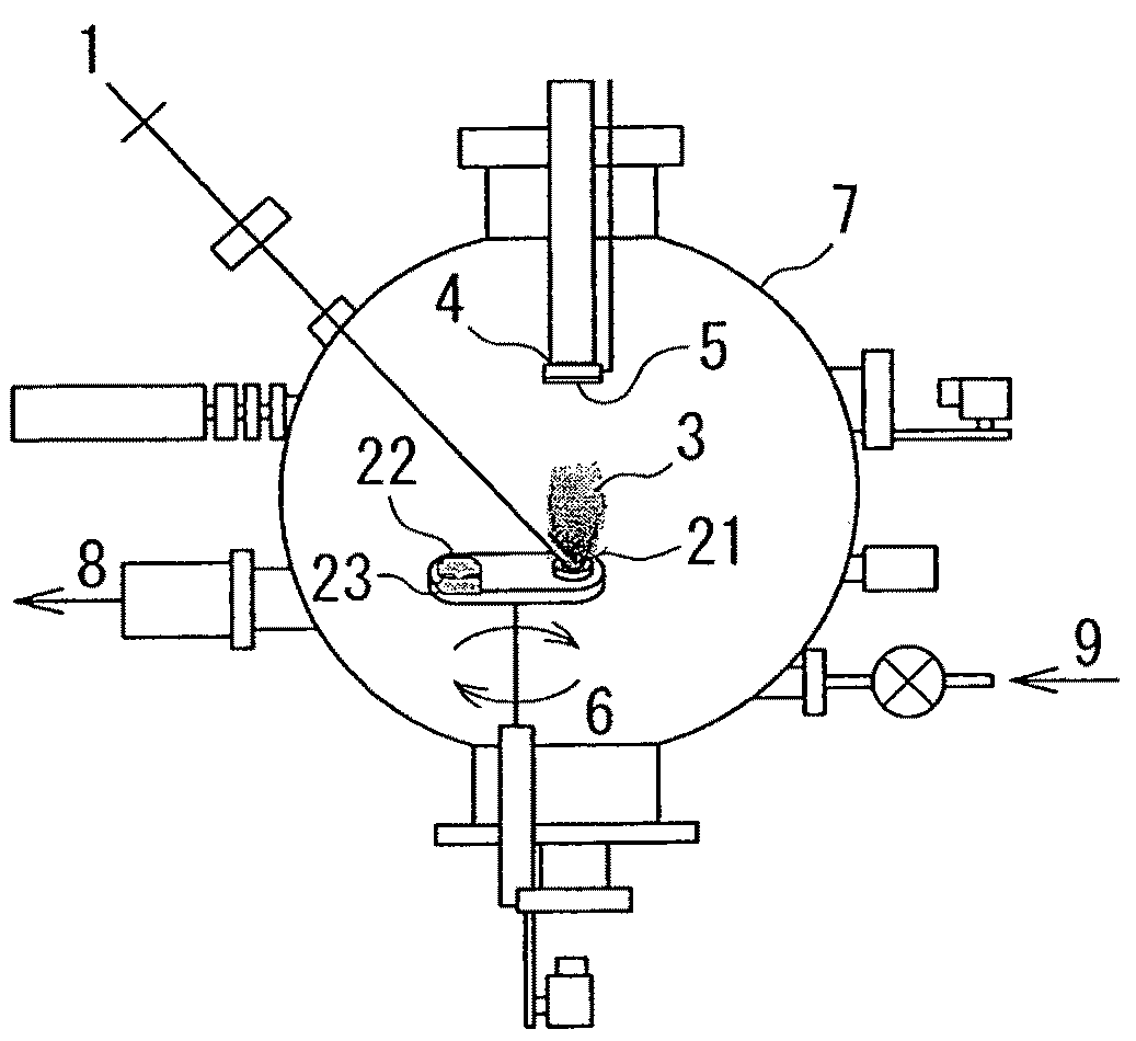
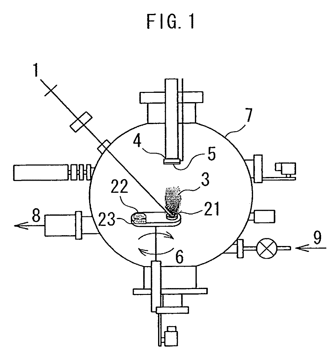
[0041]The present invention will be described with reference to the accompanying drawings. Description will first be made on a magnetic potential of a thick film having nano-crystalline texture according to the present invention composed of αFe and R2TM14B and made by using pulsed laser disposition (PLD) or strip cast method. In the description, the thick film is defined as a film having a thickness of about 50 μm or more.

[0042]For example, if a high saturation magnetization αFe to be exchange-coupled to a high coercive R2TM14B is present, the αFe first undergoes magnetization reversal in a reverse magnetic field, which constitutes a major cause of decrease of the coercivity, HcJ, of the entire magnet. If the size of the αFe is set to the magnetic domain wall width or less, non-uniform magnetization reversal in the reverse magnetic field is reduced. As a result, the coercivity, HcJ, of the entire magnet is influenced by the magnetic anisotropy of the R2TM14B and therefore is suppres...


PUM

PropertyMeasurementUnit
remanenceaaaaaaaaaa
thicknessaaaaaaaaaa
thicknessaaaaaaaaaa

Abstract

A method of manufacturing a rotor magnet for a micro rotary electric machine is provided which includes steps of: a process in which a plurality of thick films, each of which is made of nanocomposite texture composed of αFe and R-TM-B where R is either 10 to 20 atomic % Nd or 10 to 20 atomic % Pr, B is 5 to 20 atomic % and TM is either Fe or partly Co-substituted Fe with 0 to atomic %, are formed into a laminated magnet including isotropic nano-crystalline texture which contains αFe and R2TM14B and which has a remanence, Mr, of 0.95 T or more; and a process where the laminated magnet is multi-polar magnetized in-plane of the thick films.

Description

BACKGROUND OF THE INVENTION[0001]1. Field of the Invention[0002]The present invention relates to a method of manufacturing a rotor magnet for a micro rotary electric machine, and more particularly to a method of manufacturing a rotor magnet including a predetermined number of thick films layered on one another, which include magnetically isotropic nano-crystalline texture composed of a high saturation magnetized αFe phase and a high coercive R2TM14B phase, and which are multi-polar magnetized in-plane, to thereby provide a radial gap type micro rotary electric machine adapted to improve a high mechanical output power.[0003]2. Description of the Related Art[0004]A rotary electric machine for application field, for example, information and telecommunication devices has been commercially produced with its volume reduced to about 100 mm3 and is widely used. Such a rotary electric machine, when further miniaturized successfully, is expected to create a market for a motor adapted to outpu...

Claims


Application Information

Patent Timeline
Patent Type & Authority Applications(United States)
IPC IPC(8): H02K15/03H01F41/14
CPCB82Y25/00H01F1/0579H01F10/126H01F10/3222H01F41/205Y10T29/49078H02K15/03Y10T29/49012Y10T29/49075Y10T29/49009H02K1/02
Inventor YAMASHITA, FUMITOSHI
Owner MINEBEA CO LTD
Why Eureka
Try Eureka