Method of Making a Hybrid Metal-Plastic Heat Exchanger

a heat exchanger and metal-plastic technology, applied in indirect heat exchangers, lighting and heating apparatuses, other domestic objects, etc., can solve the problems of poor corrosion resistance, high manufacturing cost, high brazing temperature, etc., and achieve simple heat exchanger design, high heat exchange efficiency, and low manufacturing cost

Inactive Publication Date: 2010-02-25
DELPHI TECH INC
View PDF18 Cites 17 Cited by
  • Summary
  • Abstract
  • Description
  • Claims
  • Application Information

AI Technical Summary

Benefits of technology

[0008]The benefits of this method of manufacturing a hybrid plastic and metal heat exchanger includes a simpler heat exchanger design, lower material cost, lower manufacturing cost, and energy savings in the manufacturing process. Further features and advantages of the invention will appear more clearly on a reading of the following detailed description of an embodiment of the invention, which is given by way of non-limiting example only and with reference to the accompanying drawings.

Problems solved by technology

Thermally conductive plastics overcome some undesirable attributes of metals including poor corrosion resistance, high brazing temperature and high manufacturing cost.
However, they have their own limitations including low strength, high permeability and low thermal conductivity.
Of these shortcomings, lower thermal conductivity had been most difficult to overcome.
Typically, they are utilized in applications that are highly corrosive and their operating temperatures are under 300° F. However, these materials do not transfer heat as well as metals and accordingly where the heat transfer rates tend to be low; such as on the air side of compact heat exchangers in automotive heating and cooling applications, their use must be kept to a minimum.

Method used


Image

  • Method of Making a Hybrid Metal-Plastic Heat Exchanger
  • Method of Making a Hybrid Metal-Plastic Heat Exchanger
  • Method of Making a Hybrid Metal-Plastic Heat Exchanger

Examples


Embodiment Construction

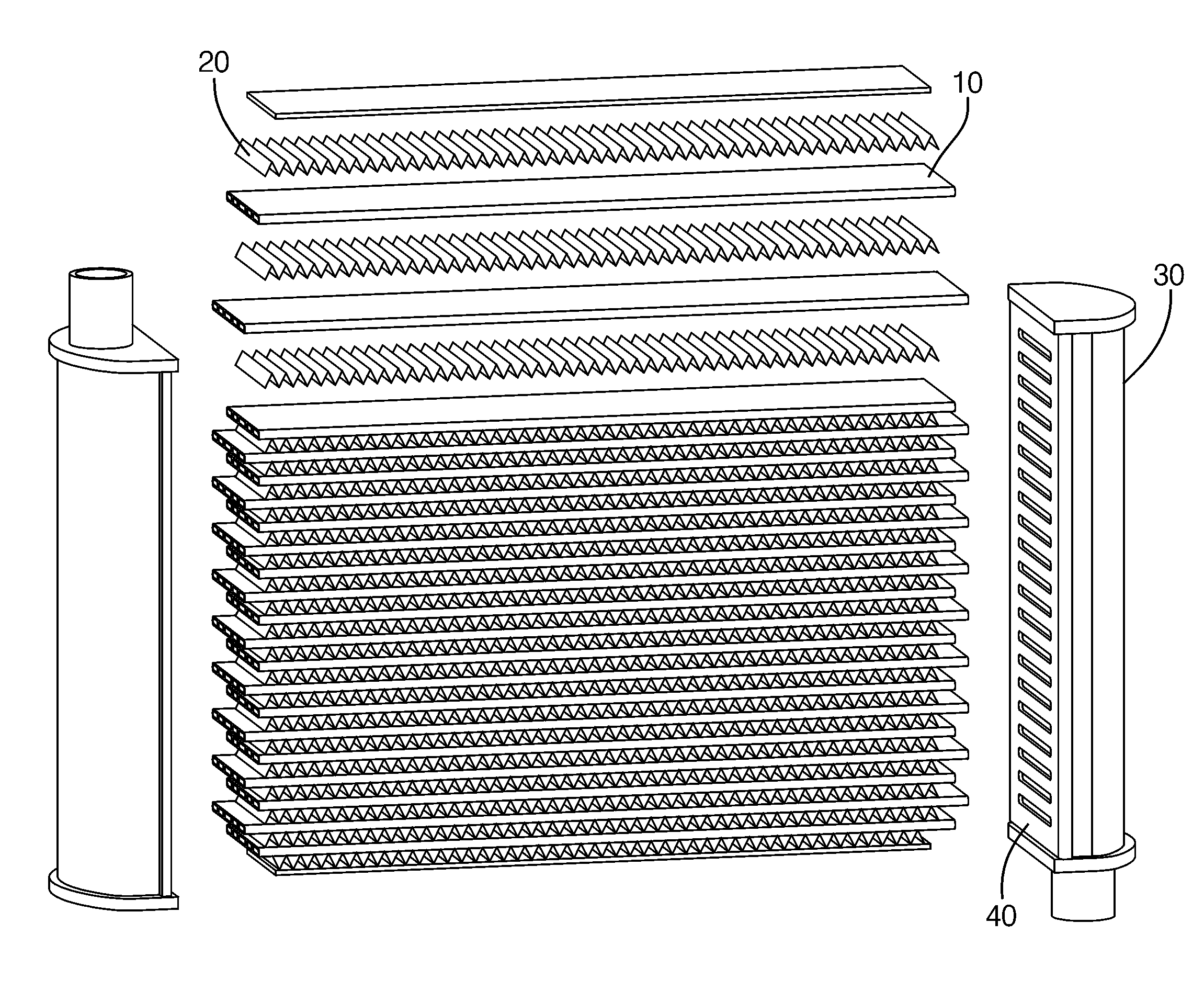
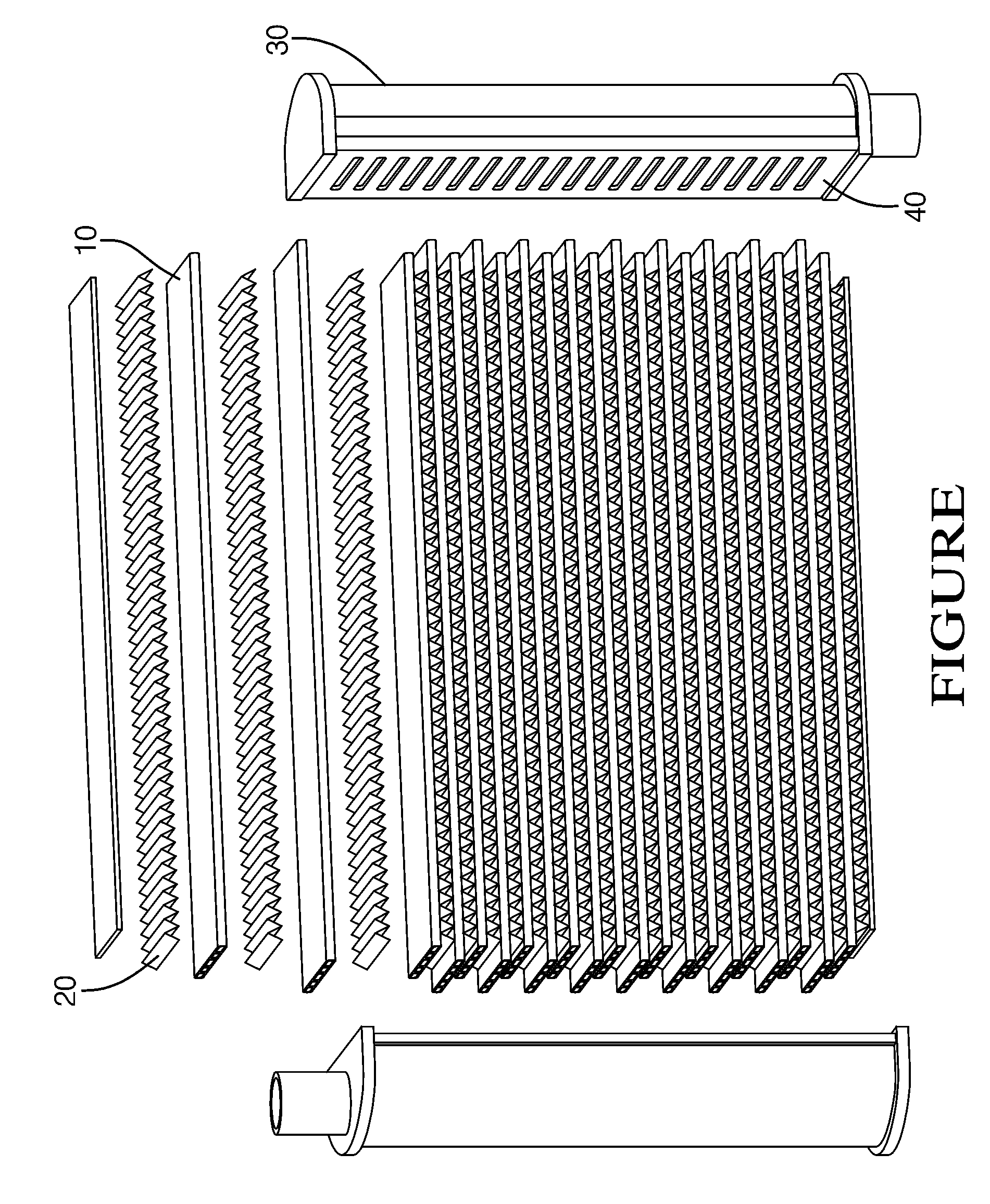
[0011]Shown in FIG. 1 is a metal-plastic hybrid heat exchanger that includes a plurality of plastic tubes 10, metal fins 20, plastic tanks 30 and plastic headers 40. Presented below are the design considerations in the selection of these materials as well as in the method of bonding the metal fins 20 and plastic headers 40 to the plastic tubes 10.

Selection of Plastic Tubes

[0012]Selection of the plastic tubes 10 is dictated by the desire to improve the corrosion resistance on the coolant side of the heat exchanger and to reduce the material cost of the heat exchanger. Since the thermal conductivity and the tensile strength of the conventional plastics are lower than those of metal, it is desirable that new plastic materials with improved strength and thermal conductivity be used. The tensile strength of the new plastic materials is comparable with that of aluminum suggesting that reasonably thin-walled plastic tubes 10 can be employed. However, the thermal conductivity of the new pla...


PUM

PropertyMeasurementUnit
temperatureaaaaaaaaaa
melting pointaaaaaaaaaa
operating temperaturesaaaaaaaaaa

Abstract

A method of manufacturing a metal-plastic hybrid heat exchanger including the steps of providing a plurality of metallic fins, providing a plastic tank with a melting point above a predetermined temperature and having a header plate that includes a plurality slots, and providing a plurality of plastic tubes with a melting point above the predetermined temperature. The plastic tubes are inserted into the corresponding slots of the plastic tank to form an assembly. The metal fins are inserted between the plastic tubes of the assembly. A thermoplastic adhesive is applied onto the mating surfaces of the metal fins and the plastic tubes, and onto mating surfaces of the slots and the plastic tubes of the assembly. The metal plastic heat exchanger assembly is then heated with infrared radiation to the predetermined temperature to cure the thermoplastic adhesive, thereby bonding the metal fins and the slotted headers to the tubes.

Description

[0001]This application claims the benefit of U.S. provisional patent application Ser. No. 61 / 188,702 for a HYBRID HEAT EXCHANGER AND METHOD OF MAKING THE SAME, filed on Aug. 12, 2008, which is hereby incorporated by reference in its entirety. This claim is made under 35 U.S.C. §119(e); 37 C.F.R. §1.78; and 65 Fed. Reg. 50093.TECHNICAL FIELD OF INVENTION[0002]The invention relates to a method of making a heat exchanger; more particularly, a metal-plastic heat exchanger.BACKGROUND[0003]Most heat exchangers for high temperature applications are made of metals or ceramics in view of their high melting temperature, high strength and high thermal conductivity needs. For moderate temperature applications, such as for automotive heating and cooling, the heat exchangers are made of metals such as copper and aluminum although they can be made of alternate materials such as thermally conductive plastics. Thermally conductive plastics overcome some undesirable attributes of metals including poo...

Claims


Application Information

Patent Timeline
Patent Type & Authority Applications(United States)
IPC IPC(8): B23P15/26
CPCB23P15/26Y10T29/49378B29C66/73115B29C66/73116B29C66/742B29C66/919B29C2035/0822B29K2023/00B29K2027/12B29K2077/00B29K2101/12B29K2105/0079B29K2305/00B29K2305/02B29K2305/10B29L2031/18F28D1/05383F28F1/126F28F9/162F28F21/062F28F21/067F28F2275/025B29C66/91411B29C66/543B29C66/91935B29C65/1483B29C65/4835B29C65/485B29C65/1412B29C66/71B29C66/7212B29C66/7392B29K2309/08
Inventor BHATTI, MOHINDER SINGH
Owner DELPHI TECH INC
Why Eureka
Try Eureka