Transmission for industrial vehicle

a technology for industrial vehicles and transmission lines, applied in mechanical equipment, transportation and packaging, gearboxes, etc., can solve the problems of complex configuration of oil lines for providing hydraulic pressure to hydraulic clutches, poor power transmission of torque converters, and inability to meet the needs of industrial vehicles, etc., to achieve rapid increase in load or at other times, avoid engine stoppage, and improve efficiency

Inactive Publication Date: 2010-02-25
KOMATSU LTD
View PDF14 Cites 5 Cited by
  • Summary
  • Abstract
  • Description
  • Claims
  • Application Information

AI Technical Summary

Benefits of technology

[0025]In this case, the engine power can be transmitted with good efficiency because the rotation from the engine is transmitted to the transmission mechanisms by a main clutch device rather than a torque converter. The main clutch device can control the clutch capacity by controlling the hydraulic pressure of the clutch in the case of a hydraulic clutch, for example. Therefore, engine stoppage under a rapid increase in load or at other times can be avoided by reducing the clutch capacity of the main clutch device.

Problems solved by technology

The torque converter has poor power transmission because power is transmitted using a fluid.
Also, a conventional transmission has a hydraulic clutch provided to each speed-change step, so the configuration is complex, and the configuration of the oil lines for providing hydraulic pressure to the hydraulic clutch is complicated.
However, in a transmission for an industrial vehicle, the reverse-movement side is similar to the forward-movement side in that a plurality of speed-change steps is required in the same manner as during forward travel, and a configuration such as that shown in Japanese Laid-open Patent Application No. 2001-99246 cannot be used without modification.

Method used


Image

  • Transmission for industrial vehicle
  • Transmission for industrial vehicle
  • Transmission for industrial vehicle

Examples


Embodiment Construction

Overall Structure

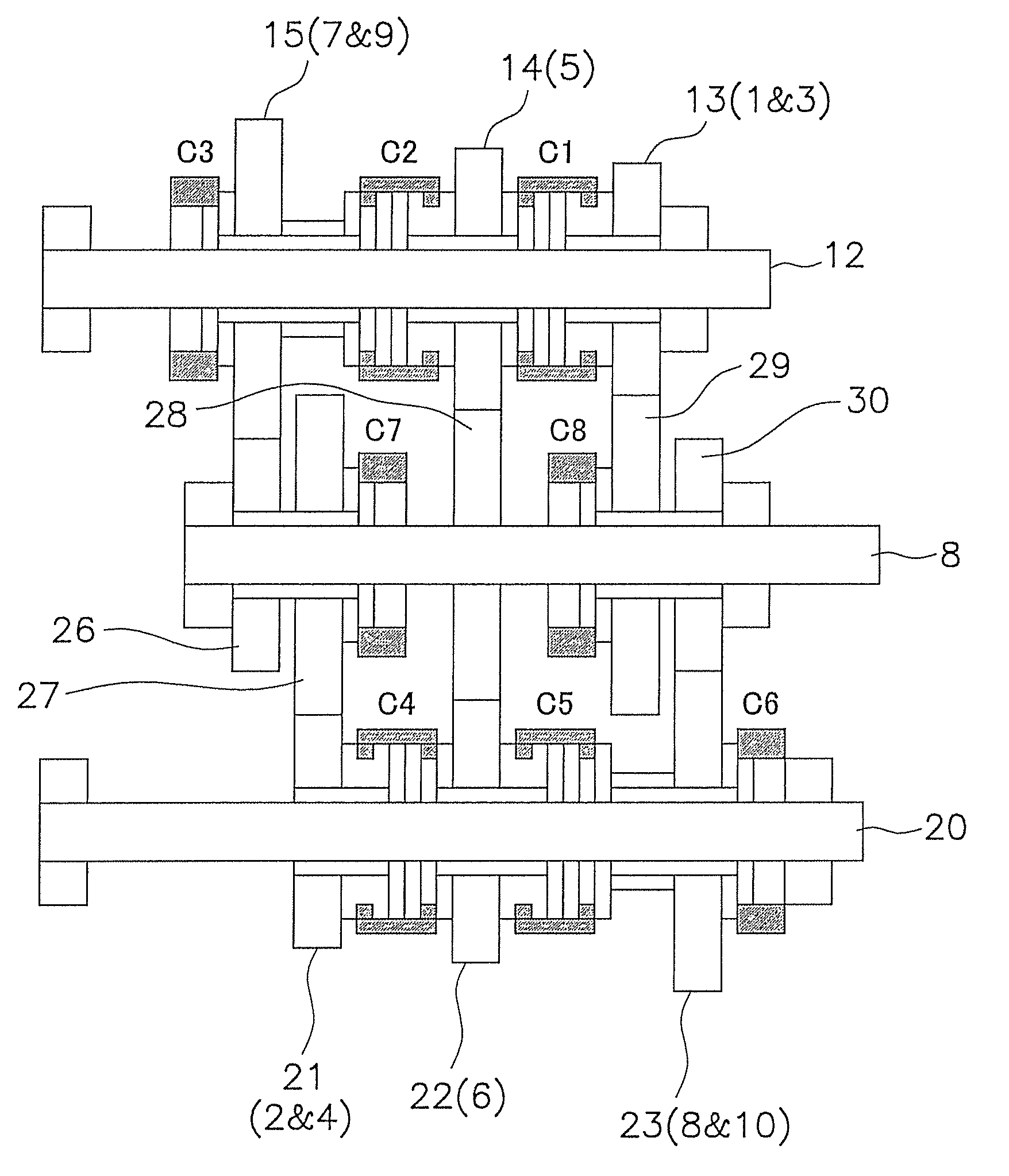
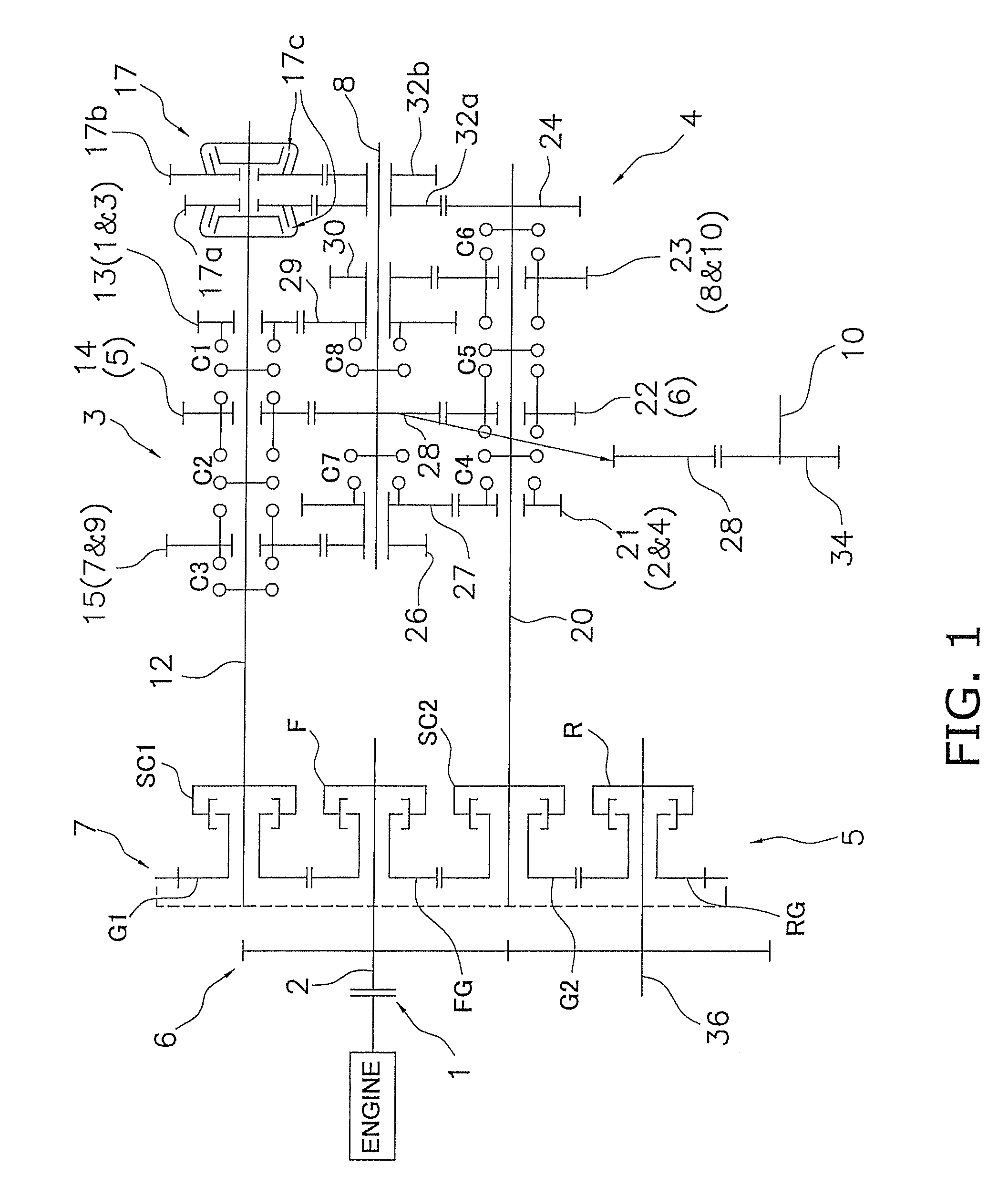
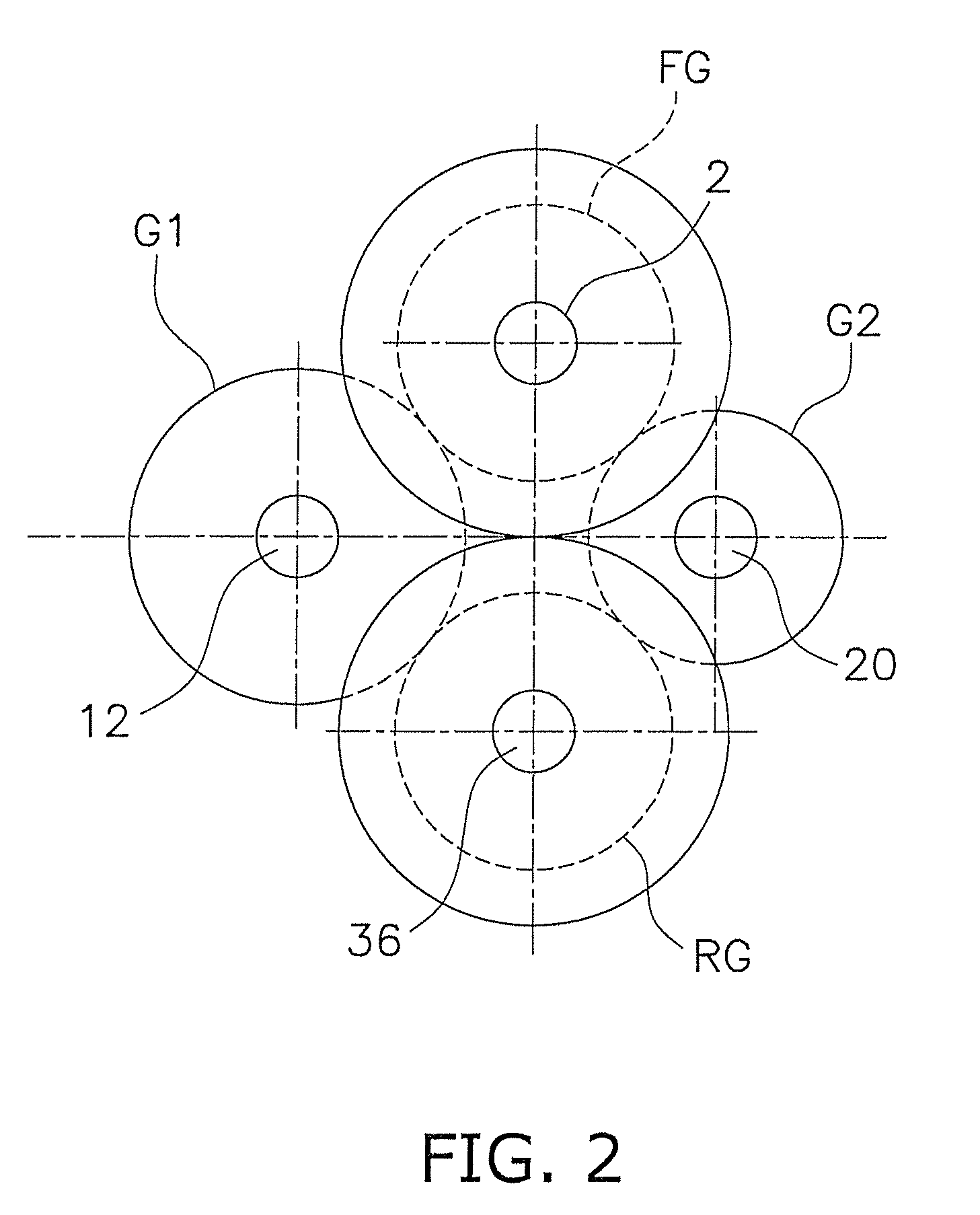
[0038]FIG. 1 is a skeleton view of the transmission according to an embodiment of the present invention. FIG. 2 is a general schematic view of the shafts and the like as seen from the engine side of the transmission. FIG. 3 is a schematic partial view of the transmission mechanism. In FIG. 2, only the arrangement of some of the shafts and the like is shown, and the configuration of the output shaft and the like has been omitted.

[0039]The transmission shown in FIG. 1 is installed, e.g., in a wheel loader, and is provided with ten speed-change steps for both forward and reverse travel. The transmission has a main clutch 1 to which rotation from the engine is inputted, an input shaft 2 to which the engine rotation is inputted via the main clutch 1, a first transmission mechanism 3, a second transmission mechanism 4, a clutch mechanism 5, a rotation direction switching gear train 6, a speed change gear train 7, and an output shaft 10. A speed-changing idle shaft 8 is di...


PUM


Abstract

A transmission for an industrial vehicle has an input shaft, first and second transmission mechanisms, a clutch mechanism, a rotation direction switching gear train, a speed change gear train, and an output shaft. The first and second transmission mechanisms change the speed among a plurality of speeds of rotation from the input shaft. The clutch mechanism is disposed on the input side of the transmission mechanisms and includes forward and reverse clutches and first and second snap clutches for selecting which of the first and second transmission mechanisms will receive rotational input from the engine. The rotation direction switching gear train inputs rotations for forward and reverse travel to the forward and reverse clutches. The speed change gear train inputs to the first snap clutch and the second snap clutch the output from the forward clutch and the reverse clutch.

Description

CROSS-REFERENCE TO RELATED APPLICATIONS[0001]This national phase application claims priority to Japanese Patent Application No. 2007-071971, filed on Mar. 20, 2007. The entire disclosure of Japanese Patent Application No. 2007-071971 is hereby incorporated herein by reference.TECHNICAL FIELD[0002]The present invention relates to a transmission for an industrial vehicle, particularly to a transmission for an industrial vehicle for changing and outputting the speed of rotation from the engine while capable of multiple speed changes during forward and reverse travel.BACKGROUND ART[0003]A hydraulic transmission such as that disclosed in Japanese Laid-open Patent Application No. 2005-282830 is commonly provided as a transmission for a wheel loader or another industrial vehicle. This type of transmission has a torque converter disposed between the engine and the transmission body. Disposed inside the transmission body are a hydraulic clutch for forward travel and a hydraulic clutch for re...

Claims


Application Information

Patent Timeline
Patent Type & Authority Applications(United States)
IPC IPC(8): F16H37/06
CPCF16H3/093F16H37/043F16H2200/0065Y10T74/19056Y10T74/19084Y10T74/19223Y10T74/19233
Inventor TAKESHIMA, HIROAKI
Owner KOMATSU LTD
Why Eureka
Try Eureka