Solar collector system

a solar collector and collector technology, applied in solar heat systems, heat collector mounting/supports, light and heating equipment, etc., can solve the problems of reducing the degree of concentration that can be obtained, the frame of this type of collecting system is very expensive, and the piping may develop leaks, so as to maximize the absorption

Inactive Publication Date: 2010-02-25
ORMAT TECH INC
View PDF14 Cites 9 Cited by
  • Summary
  • Abstract
  • Description
  • Claims
  • Application Information

AI Technical Summary

Benefits of technology

[0018]The present invention also provides a stationary preferably flat plate receiver facing downwards, absorbing the solar energy reflected upwards. The receiver preferably comprises a metal absorbing plate, fluid-carrying tubes, thermal insulation and preferably a black material front for maximizing the absorption. A control is provided to direct radiation away from the receiver in the event of danger of overheating of the receiver or during periods of maintenance.

Problems solved by technology

The frame of this type of collecting system is very expensive and flexible piping needs to be used to convey the fluid heated in the receiver, the piping of which may develop leaks due to the constant movement of the system.
Another difficulty found in prior art collectors is related to the paraxial errors, which reduce the sharpness of the solar radiation focused onto the receiver and thereby bring about a reduction in the degree of concentration that can be obtained.
The paraxial errors occur when the solar beam is not paraxial with the optical axis of the concentrator.
Consequently, a serious deficiency in the performance of the concentrator is produced since the paraxial departure angle varies from hour to hour and from day to day.
Since the aberration error and the defocusing error can partially or completely overlap, the larger of these errors determines the maximum concentration factor obtainable with this being further limited by the angular size of the solar disc.
Further difficulties that occur in prior art systems are the thermal heat losses due to the increase in operating temperatures above the ambient temperature.
However, the apparatus can only perform simultaneous tracking for each coupled reflector, and does not enable different tracking for each of the reflectors.
However, the system performs two axis movement and uses a plurality of reflector segments, making it expensive and complex to manufacture.

Method used


Image

  • Solar collector system
  • Solar collector system
  • Solar collector system

Examples


Embodiment Construction

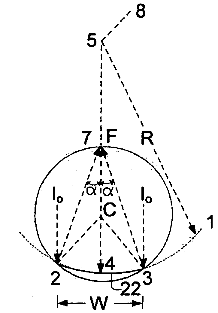
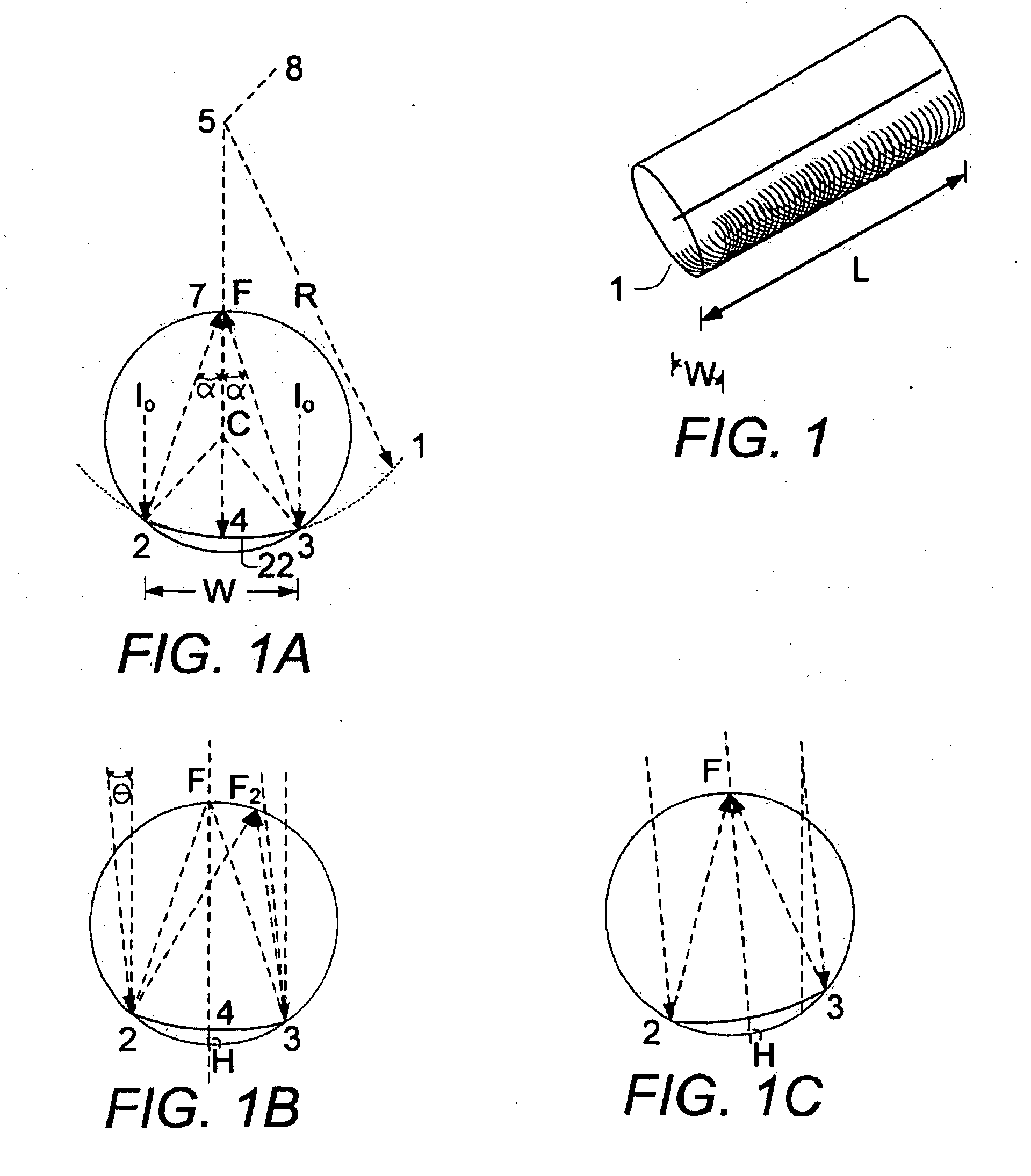
[0045]As used herein the term “tracking” refers to a process in which the reflector follow the motion of the sun. The present invention can be better understood by reference to FIG. 1A, FIG. 1B and FIG. 1C which cover the basic physics which is advantageously exploited in the present invention.

[0046]FIG. 1A shows mirror 2-3 of width W, which concentrates a beam of solar radiation onto a receiver (not shown) in the focal region F. The beam is paraxial and if the profile is parabolic, the concentrated beam forms a thin line of energy on the receiver. However, if the beam is not paraxial, but tilted at an angle (θ), an image of concentrated light is formed at F2 (see FIG. 1B). Whatever the paraxial departure (θ) is, the image always falls on the cc, the circumscribing circle, that passes through the mirror extremities 2 and 3 and the focus F. The center of this circle is at C, C being a geometrical property of the mirror so that if the mirror moves, C moves with it. The central area of...


PUM


Abstract

The present invention provides a solar collector apparatus, comprising a horizontally-mounted cylindrical reflector, divided along its length into two reflector segments, each having its own axis of rotation. Preferably, the two reflector segments are produced by dividing the horizontally-mounted cylindrical reflector down its centerline into two equal reflector segments. The two reflectors segments perform novel tracking with different rotation angles about their corresponding axes by use of a trapeze coupling or a mechanism that permits separate tracking. Since the two reflector segments are coupled, preferably only one tracking mechanism (trapezoid or other) is required since the reflector segments preferably have parallel axes.
The present invention also provides a stationary preferably flat plate receiver facing downwards, absorbing the solar energy reflected upwards. The receiver preferably comprises a metal absorbing plate, fluid-carrying tubes, thermal insulation and preferably a black material front for maximizing the absorption. A control is provided to direct radiation away from the receiver in the event of danger of overheating of the receiver or during periods of maintenance.

Description

FIELD OF THE INVENTION[0001]The present invention relates to the field of solar energy and to the concentration of solar radiation for producing heat and / or electricity. More particularly, the present invention relates to a solar collecting system that concentrates solar radiation onto receivers using solar collectors.BACKGROUND OF THE INVENTION[0002]In solar collector systems known in the art, solar radiation is concentrated by a reflector or reflectors onto a receiver, which converts the solar radiation into heat or electricity. The reflector or reflectors follow the movement of the sun in order to reflect solar energy efficiently onto the receiver. This operation is termed “tracking”. Single-dimension tracking systems known in the art can perform seasonal tracking from north to south or daily tracking from east to west. The reflector used in the prior art can be of cylindrical form and the receiver is of the form known in the art as a “flat type receiver”, or a horizontal tube or...

Claims


Application Information

Patent Timeline
Patent Type & Authority Applications(United States)
IPC IPC(8): F24J2/38F24S23/74F24S50/20
CPCY02E10/45Y02E10/47F24J2002/1042F24J2/07F24J2/14F24J2/18Y02E10/41F24J2/5264F24J2/541F24J2002/0084F24J2002/5451F24J2002/5472F24J2/523F24S20/20F24S23/74F24S23/79F24S25/10F24S25/70F24S30/425F24S2020/16F24S2023/838F24S2030/131F24S2030/137Y02E10/40
Inventor TABOR, HARRY ZVI
Owner ORMAT TECH INC
Why Eureka
Try Eureka