Double-gear driving mechanism for a reel unit

a driving mechanism and reel unit technology, applied in fishing, reels, applications, etc., can solve the problems of user subconscious application of more force on the crank handle, significant wear or even fracture of the top portion, undesirable for the user, etc., to increase the volume of the reel unit, increase the overall bearing capacity, and keep the speed of unwinding and rewinding. the effect of speed

Inactive Publication Date: 2010-02-25
TAO
View PDF0 Cites 2 Cited by
  • Summary
  • Abstract
  • Description
  • Claims
  • Application Information

AI Technical Summary

Benefits of technology

[0003]The present invention aims to overcome the aforesaid shortcomings of the prior art. To this end, the present invention provides a double-gear driving mechanism for a reel unit, which can enhance the overall bearing capacity to the rotor drive shaft of the reel unit on the premise that without increasing the volume of the reel unit as well as keeping the velocity of unwinding and rewinding.
[0012]1. By use of an idle pinion, the present invention provides a double-gear drive mode of the rotor drive shaft. This increases the lifting capability of the rotor drive shaft while the original strength of the pinion teeth still remaining unchanged;
[0013]2. The present invention employs a small-module gear system, so a reel unit featuring a high specific speed can obtain without increasing the volume of the reel unit;
[0014]3. The idle pinion of the present invention can drive the cam shaft to move the reciprocating shaft and consequently the line enclosure to move reciprocally;
[0015]4. As the master gear shaft and the master gears of the present invention are connected by use of a snap ring and an elastic ring, high precision requirements on individual components are eliminated, which is favorable for mating between the individual components.

Problems solved by technology

However, when fishing a fish of larger size, the user tends to subconsciously apply more force to the crank handle.
In this case, top portions of the pinion teeth are subjected to a substantial force that may possibly cause significant wear or even fracture of the top portions, which is undesirable for the user.

Method used


Image

  • Double-gear driving mechanism for a reel unit
  • Double-gear driving mechanism for a reel unit
  • Double-gear driving mechanism for a reel unit

Examples


embodiment 2

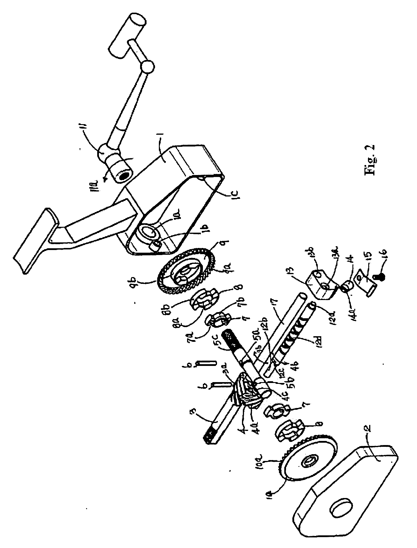
[0056]Embodiment 2 differs from Embodiment 1 only in that, it is another technical project, its aim is to simplify the structure of the assembly comprised of the second master gear and the first master gear, only one of the master gears (e.g., the second master gear 10) is connected with the master gear shaft 5 by use of an additional elastic ring 8, while the first master gear is connected with the mast gear shaft 5 directly in a rigid way (e.g., using a common spline), or the master gear shaft 5 and the first master gear 9 may be formed integrally as a unitary piece, as shown in FIG. 7. Alternatively, the second master gear 10 may be formed integrally with the master gear shaft 5 while the first master gear is connected with the master gear shaft 5 via the elastic ring 8.


PUM


Abstract

A double-gear driving mechanism for a reel unit comprises a reel chamber in which a rotor drive shaft is disposed longitudinally and a master gear shaft is disposed laterally. A main gear is formed around a periphery of the drive shaft, and a first master gear is fixed on one end of the master gear shaft. A crank handle is connected to a male thread portion of the master gear shaft. The inner teeth around a periphery of the first master gear engage the teeth of the main gear. An idle pinion provided on the other side of the drive shaft in parallel and it engages the main gear. On the other end of the master gear shaft is fixed a second master gear, inner teeth of which engage the teeth of the idle pinion. The present invention provides a double-gear drive mode of the rotor drive shaft by using the idle pinion. This increases the lifting capability of the rotor drive shaft while the original strength of the pinion teeth still remaining unchanged. Meanwhile, the double-gear driving mechanism of the present invention features a high specific speed, at the same time it is easy to manufacture and exhibits good mating conditions.

Description

TECHNICAL FIELD[0001]The present invention relates to a fishing tackle, and more particularly, to a double-gear driving mechanism for a reel unit.BACKGROUND ART[0002]In order to reduce volume and to unwind or rewind the fishing line as quickly as possible, fishing reels currently available are all designed to unwind or rewind the fishing line by manually operating a crank handle to drive a small-module single-gear driving mechanism which in turn drives a rotor to rotate. Meanwhile, for the purpose to reduce the weight, the gear is made to have a limited strength. This kind of structure works well for fishing of small size fish. However, when fishing a fish of larger size, the user tends to subconsciously apply more force to the crank handle. In this case, top portions of the pinion teeth are subjected to a substantial force that may possibly cause significant wear or even fracture of the top portions, which is undesirable for the user.BRIEF SUMMARY OF THE INVENTION[0003]The present ...

Claims


Application Information

Patent Timeline
Patent Type & Authority Applications(United States)
IPC IPC(8): A01K89/01A01K89/00
CPCA01K89/01
Inventor TAO, NING
Owner TAO
Why Eureka
Try Eureka