Joint structure of cable racks

a joint structure and cable rack technology, applied in the direction of screwdrivers, threaded fasteners, machine supports, etc., can solve the problems of difficulty in further peeling of film, time and effort, and current cannot bypass therethrough, and achieves sufficient electrical conduction, large friction resistance, and minimal time and effort

Inactive Publication Date: 2010-02-25
BURESUTO INDS
View PDF3 Cites 12 Cited by
  • Summary
  • Abstract
  • Description
  • Claims
  • Application Information

AI Technical Summary

Benefits of technology

[0019]As above, in the cable rack joint structure of the present invention, the bolt insertion hole (9) is formed in a circular shape which allows only a distal end of the neck portion (6) of the joint bolt (5) to be inserted thereinto, wherein the bolt insertion hole (9) has a plurality of recesses (9A) formed in an inner peripheral surface thereof and adapted to lock respectively at least two of three or more corner edges (6A) of the neck portion (6), in such a manner that the inner peripheral surface of the bolt insertion hole (9) is bit into thereby at respective positions where the corner edges (6A) of the neck portion (6) are locked by corresponding ones of the recesses (9A). This makes it possible to reliably prevent corotation which otherwise occurs between a bolt and a nut, such as a hot-dip galvanized bolt and nut, while tightly fastening them together. In addition, each of the recesses (9A) is formed in the inner peripheral surface of the circular bolt insertion hole (9) in the form of a slight depression lockingly engageable with a corresponding one of the corner edges (6A). This makes it possible to allow a shape of the bolt insertion hole (9) to be intuitively recognized as being that of a standard bolt insertion hole to minimize the time and effort needed on activities for making operators become familiarized with the bolt insertion hole (9) so they know it is a proper bolt hole.
[0020]In the present invention, the joint bolt (5) and the locking nut (7) having a particular surface-finishing film, such as a hot-dip galvanizing film, coated on the entire surface including a threaded portion thereof (as set forth in the appended claim 2), can be effectively used while reliably preventing a corotation phenomenon which particularly occurs due to a relatively large frictional resistance between external threads of the joint bolt (5) and internal threads of the locking nut (7).
[0021]According to the configuration/arrangement (as set forth in each of the appended claims 3 to 6),

Problems solved by technology

However, if cable racks with such a surface finish are installed by simply joining them together, it is undesirable because they will be incapable of electrical conduction therebetween because such a surface finish film has no electrical conductivity.
This causes a problem that, when current leakage occurs in a cable laid out along the cable racks incapable of mutual electrical conduction, the current cannot bypass therethrough.
In the above conventional techniques, there remain problems that a lot of time and effort are required for conducting the cable-rack joining operation in the structure stated in Japanese Utility Model Publication No. 55-043700B, and peeled film fractions ride on the protrusion or the like-like portions which causes difficulty in further peeling the film in the structures stated in Japanese Utility Model Laid-open No. 54-048399A.
Nonetheless, there still remains a problem in the technique disclosed in Japanese Patent Publication No. 04-004808B, namely, a corotation of the joint bolt and the nut while being fastened to each other.
Specifically, in a case where a frictional resistance between an externally-threaded portion of the bolt and an internally-threaded portion of the nut is relatively large, as in the case of a hot-dip galvanized bolt and nut, a torque greater than an axial force (tensile force) is likely to be imposed on the bolt when the nut is rotated, whereby a corotation phenomenon occurs in such a manner that the bolt rotates together with the nut before the neck portion of the bolt is forcibly fitted into the through-hole, which causes a failure in obtaining a tightening force and a function of establishing electrically conduction.
However, once the corota

Method used


Image

  • Joint structure of cable racks
  • Joint structure of cable racks
  • Joint structure of cable racks

Examples


Embodiment Construction

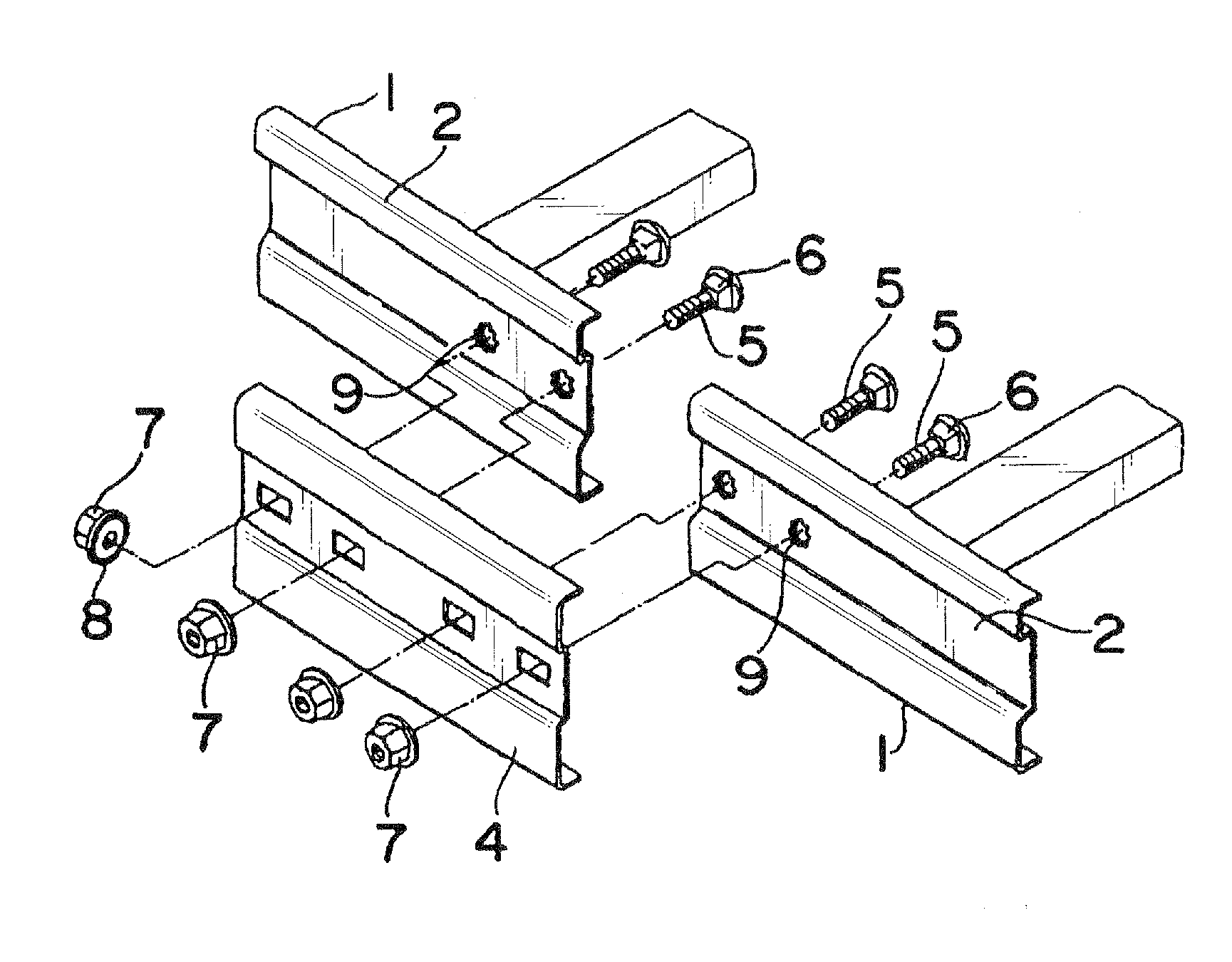
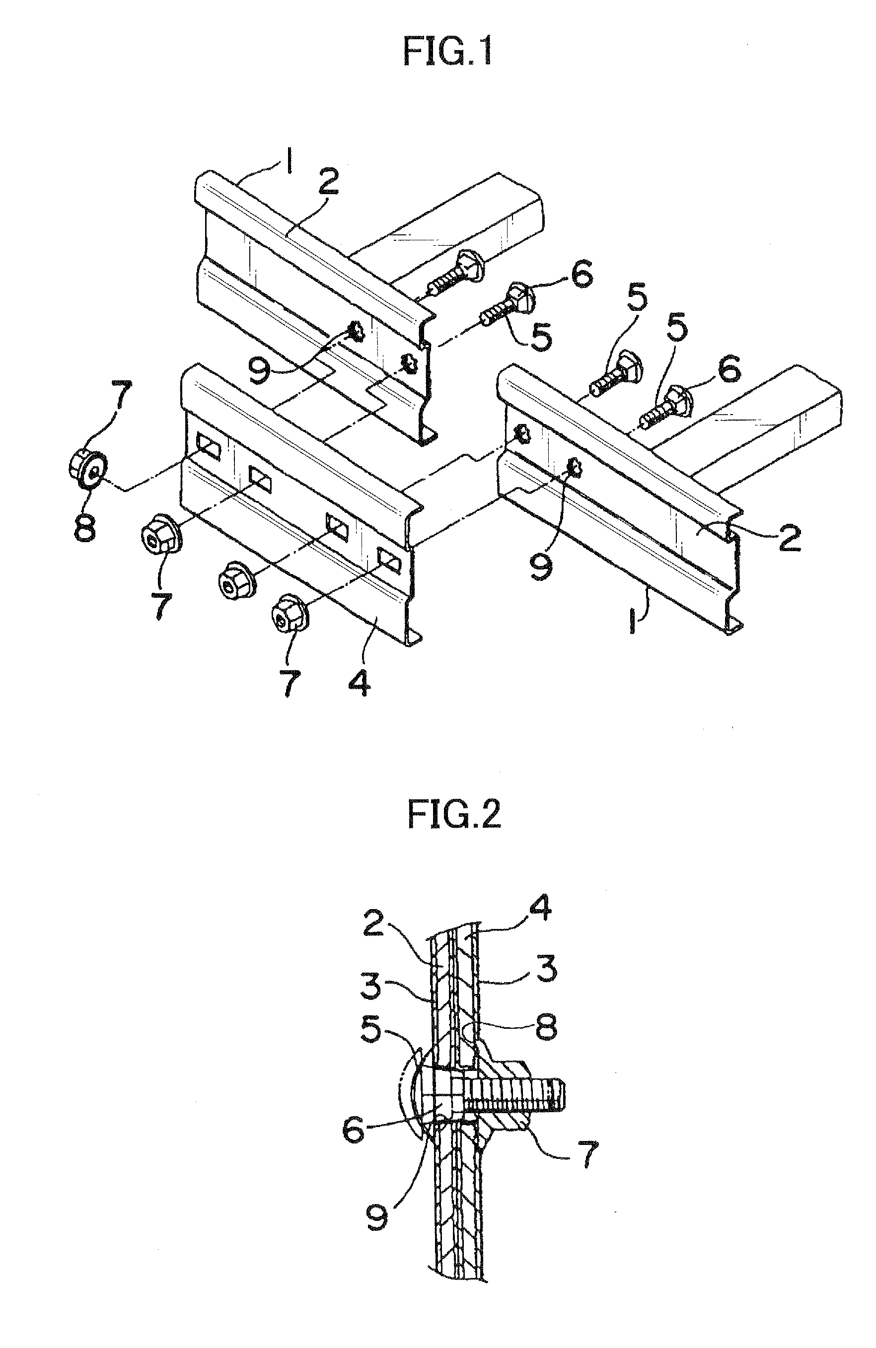
[0034]A preferred embodiment of the present invention is directed to achieving the desired object thereof in the following manner. A bolt insertion hole is formed in a circular shape so that only a distal end of a polygonal neck portion of a joint bolt can be inserted thereinto. Further, the bolt insertion hole has a plurality of recesses formed in an inner peripheral surface thereof and adapted to lock respectively at least two of three or more corner edges of the neck portion, in such a manner that they bite into an inner peripheral surface of the bolt insertion hole at respective positions of the corner edges thereof whereby the corner edges of the neck portion are locked by the corresponding ones of the recesses. When the neck portion of the joint bolt has a four-sided shape in cross-section, the recesses are formed in the inner peripheral surface of the bolt insertion hole at positions lockingly engageable respectively with an adjacent two of the four corner edges of the four-s...


PUM


Abstract

Disclosed is a cable rack joint structure, which is designed to bite into an inner peripheral surface of a bolt insertion hole so as to establish sufficient electrical conduction between cable racks. In the cable rack joint structure, a bolt insertion hole 9 is formed in a circular shape, which allows only a distal end of a polygonal neck portion 6 of a joint bolt 5 to be inserted thereinto. The bolt insertion hole 9 has a plurality of recesses 9A formed in an inner peripheral surface thereof and adapted to lock respectively at least two of three or more corner edges 6A of the neck portion 6, in such a manner that the inner peripheral surface of the bolt insertion hole 9 is bitten into at respective positions where the corner edges 6A of the neck portion 6 are locked by corresponding ones of the recesses 9A. The cable rack joint structure of the present invention can reliably prevent corotation which otherwise occurs between the joint bolt and locking nut, such as a hot-dip galvanized bolt and nut, during an operation of tightly fastening them together, and allow a shape of the bolt insertion hole to be intuitively recognized as that of a standard bolt insertion hole so as to minimize the time and effort needed on activities for familiarizing operations with the bolt insertion hole so they know it is a proper bolt insertion hole.

Description

BACKGROUND OF THE INVENTION[0001]The present invention relates to a cable rack joint structure designed to ensure electrical conduction between cable racks, and more specifically, to a cable rack joint structure designed to prevent corotation of a bolt and a nut, such as a hot-dip galvanized bolt and nut, which occurs while tightly fastening them together.[0002]Heretofore, there have been proposed various types of metal cable racks for cable wiring, which are different in shape and structure. In consideration of weather, rust, salt, moisture, and chemical resistance and the like so as to be adaptable to environmental changes in an installation site, most of the cable racks are coated with a particular surface-finishing film, such as a baked melamine coating, or an epoxy resin-based coating excellent in rust protection capability. However, if cable racks with such a surface finish are installed by simply joining them together, it is undesirable because they will be incapable of elect...

Claims


Application Information

Patent Timeline
IPC IPC(8): F16L3/00
CPCF16B33/002H02G3/0608F16B35/065
Inventor SUGAYA, KEIICHIOKI, HIDEO
Owner BURESUTO INDS
Why Eureka
Try Eureka