Electromagnetic stirrer

a technology of electromagnetic stirrer and stirrer, which is applied in the direction of lighting and heating apparatus, furniture, transportation and packaging, etc., can solve the problems of not achieving a sufficiently strong stirring force and the stirring force is not so dramatically improved, so as to prevent excellent stirring force, and reliably confine the leakage of magnetic flux

Inactive Publication Date: 2010-02-25
JAPAN SCI & TECH CORP +2
View PDF5 Cites 15 Cited by
  • Summary
  • Abstract
  • Description
  • Claims
  • Application Information

AI Technical Summary

Benefits of technology

[0016]The effect and advantages of the present invention will be described along with the findings obtained in implementing the present invention.
[0017]The inventors diligently investigated the reasons why it is difficult to always obtain an excellent stirring force even though an iron core is provided between coils in order to prevent the leakage of magnetic flux.
[0019]In FIG. 9, the vertical electromagnetic field iron core 109 is arranged on the inner side, and the rotational electromagnetic field iron core 108 is arranged on the outer side. The plates of the iron cores 108 and 109 are formed of a laminated product. Then, the vertical electromagnetic field iron core 109 and the rotational electromagnetic field iron core 108 are arranged such that the laminated direction of the vertical electromagnetic field iron core 109 is circumferential and the laminated direction of the rotational electromagnetic field iron core 108 is vertical. In other words, in order to reliably confine the leakage of magnetic flux, the iron cores 108 and 109 have magnetic anisotropy.
[0020]However, because the iron cores 108 and 109 have anisotropy, a vertical electromagnetic field causes eddy current to be carried through the iron core 108 on the outer side, and a rotational electromagnetic field causes eddy current to be carried through the iron core 109 on the inner side for occurrence of losses.
[0021]FIG. 10 shows an example in which a vertical electromagnetic field iron core is arranged on the outer side, and a rotational electromagnetic field iron core is arranged on the inner side. Similarly to the example in FIG. 9, eddy current is carried therethrough to cause losses.
[0022]In other words, such findings were obtained that in magnetic fields traveling along two axes, the influence of the other axis leads to the occurrence of eddy current in the iron core and this seems to be a cause to put a limit to stirring force.

Problems solved by technology

However, the techniques described in Patent Document 1 and Patent Document 2 have a problem that the magnetic fluxes are leaked and as the result it is difficult to obtain a sufficient stirring force.
However, when taking a look at stirring force for liquid metal inside the container, the stirring force is not so dramatically improved as compared with the case of providing the iron core.

Method used


Image

  • Electromagnetic stirrer
  • Electromagnetic stirrer
  • Electromagnetic stirrer

Examples


embodiment 1

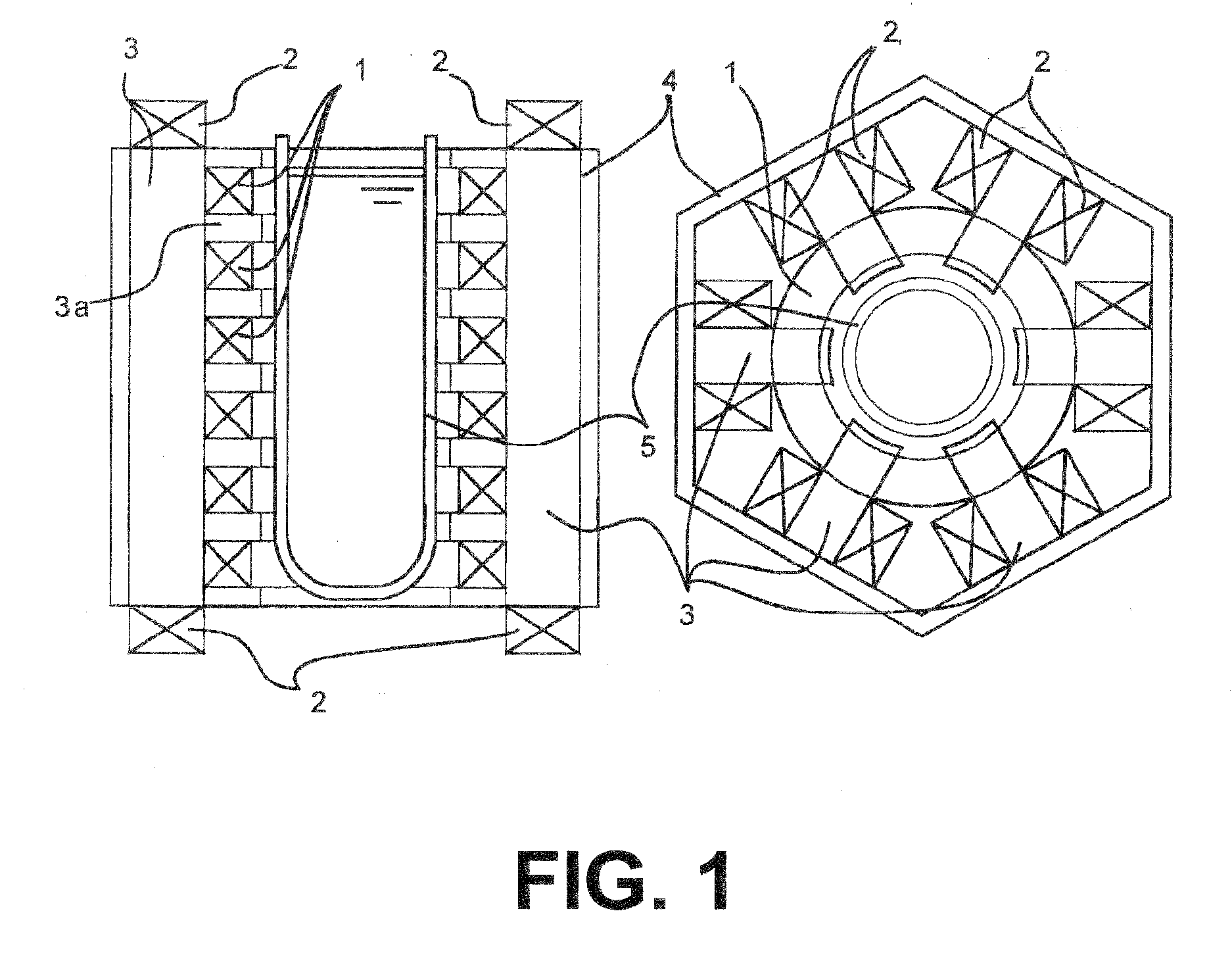
[0075]An embodiment of the present invention will be described with reference to FIG. 1.

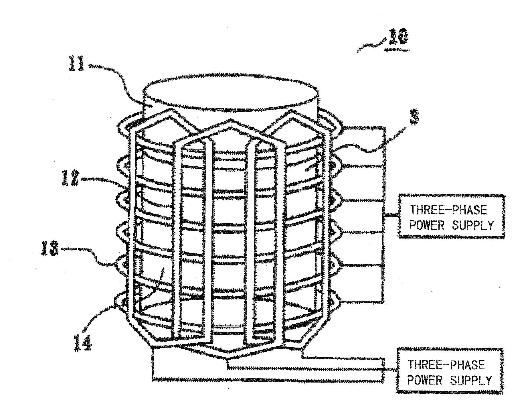
[0076]A stirrer of this embodiment has a vertical electromagnetic field generating coil 1 vertically and circumferentially provided on the outer side of a container 5, and a rotational electromagnetic field generating coil 2 provided on the outer side of the vertical electromagnetic field generating coil 1, in which an iron core 3 is inserted between the vertical electromagnetic field generating coils 1 and between the rotational electromagnetic field generating coils 2, the iron core 3 being formed of a magnetic material with magnetic isotropy and having comb teeth 3a extended to the inner surface of the vertical electromagnetic field generating coil 1.

[0077]Hereinafter, the embodiment will be described more in detail.

[0078]For the container 5, for example, a metal container having an inner diameter of 55 mm and a height of 150 mm is used. For the rotational electromagnetic field generating coil...

embodiment 2

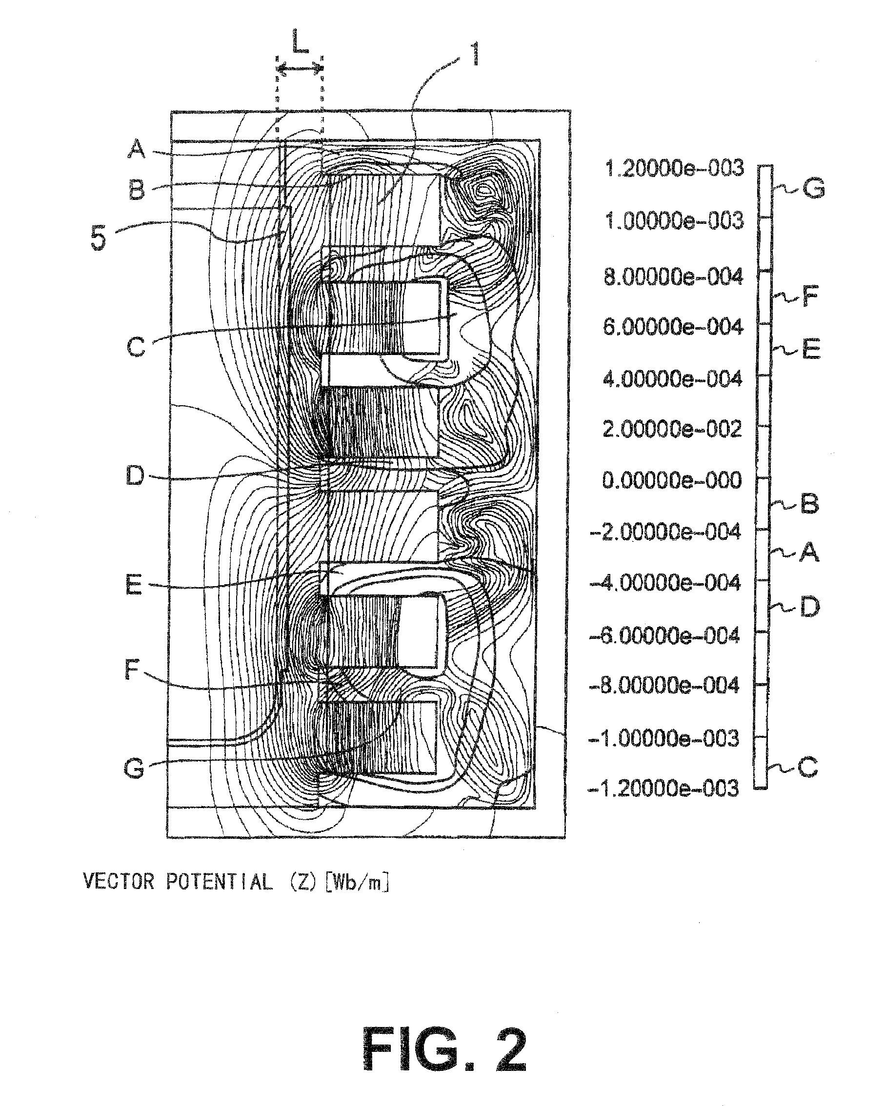
[0107]In this embodiment, the relationship between the distance (gap) (L shown in FIG. 2) from the end surface of the iron core on the inner side (that is, the end surface of the comb teeth) to liquid metal and the stirring force was determined as follows.

[0108]The electromagnetic force in the vertical direction generated in the surface of liquid metal by the vertical electromagnetic field (r=D / 2, where D is the inner diameter of the container),

Fz|r=D / 2

can be generally expressed by the following equation (Electromagnetic Processing of Materials, Research Group on Electromagnetic Processing of Materials, Iron and Steel Institute of Japan, Tohoku University Press (1999)).

Fzr=D / 2=σω2K(Brr=D / 2)2

where ω is the conductivity of liquid metal (S / m), σ is the angular frequency of applied current (rad / s), K is the wave number of the vertical magnetic field (1 / m) and

Br|r=D / 2

is the radial component (T) of the magnetic flux in the surface of liquid metal.

Br|r=D / 2

is experimentally measured by a...


PUM

PropertyMeasurementUnit
resistivityaaaaaaaaaa
heightaaaaaaaaaa
inner diameteraaaaaaaaaa

Abstract

An object is to provide an electromagnetic stirrer that can provide an excellent stirring force more than before. An electromagnetic stirrer has a vertical electromagnetic field generating coil (1) vertically and circumferentially provided on the outer side of a container (5), and a rotational electromagnetic field generating coil (2) provided on the outer side of the vertical electromagnetic field generating coil (1), in which an iron core (3) is inserted between the vertical electromagnetic field generating coils (1) and between the rotational electromagnetic field generating coils (2), the iron core (3) being formed of a magnetic material with magnetic isotropy and having comb teeth 3a extended to the inner surface of the vertical electromagnetic field generating coil (1).

Description

TECHNICAL FIELD[0001]The present invention relates to an electromagnetic stirrer, and more specifically to a double-axis electromagnetic stirrer that strongly and uniformly stirs liquid metal in a noncontact manner.BACKGROUND ART[0002]The double-axis electromagnetic stirrer is an electromagnetic stirrer that can effectively convey the magnetic fluxes of a vertical electromagnetic field and a rotational electromagnetic field to liquid metal inside a container and set the liquid metal in rotational motion and vertical motion when these electromagnetic fields are superposed on each other.[0003]Conventionally, as the double-axis electromagnetic stirrer, techniques described in Patent Document 1 and Patent Document 2 are known.[0004]In these techniques, as shown in FIG. 8, a vertical electromagnetic field generating coil 13 is circumferentially provided on the outer side of a cylindrical container 11 along the vertical direction, and a rotational electromagnetic field generating coil 12 ...

Claims


Application Information

Patent Timeline
Patent Type & Authority Applications(United States)
IPC IPC(8): C21C7/00F27D27/00
CPCB01F13/0809C21C1/06F27D27/00C22B9/003C21C5/5247Y02P10/25B01F33/451C21C7/10C22B9/22B01F33/45
Inventor TANIGUCHI, SHOJIANZAI, KOICHIUENO, KAZUYUKIITAMURA, MASAYUKISHIMASAKI, SHINICHI
Owner JAPAN SCI & TECH CORP
Why Eureka
Try Eureka