Tanks and methods of contstructing tanks

a technology of tanks and tanks, applied in the direction of tank vehicles, containers, items transportation vehicles, etc., can solve the problems of reducing the strength of tanks, affecting the movement of vehicles, and tanks are therefore prone to bulging and deformation, so as to reduce the excess venting of fumes, reduce the accumulation of excessive vapor, and increase the strength

Inactive Publication Date: 2010-02-25
REA JAMES ROBERT
View PDF10 Cites 41 Cited by
  • Summary
  • Abstract
  • Description
  • Claims
  • Application Information

AI Technical Summary

Benefits of technology

[0108]In addition, the exhaust ports allow the liquids within the tank to be removed therefrom use or disposal.
[0109]Yet a further advantage of having the passage way interconnecting adjacent compartments at the lowest point of the tank is that it may lower excess venting of fumes through the tank's exhaust ports.
[0110]This may be due to the passage way facilitating efficient movement of liquid between compartments which therefore decreases the build up of excessive vapor within the tank.
[0111]It should be appreciated from the foregoing description that the present invention has a number of advantages. Firstly, the present invention provides a method of constructing tanks from thin sheet material. Therefore, these tanks are lighter and better suited for use in vehicles.
[0112]In addition, the configuration of baffles, and sealing the tank with a section of material located inside the tank may provide increases in strength. This helps the tanks to better withstand the pressure of containing a fluid. In addition, the tanks may be stronger and better able to withstand explosions.
[0113]In addition, the present invention also decreases the sloshing of fluid within the tank.

Problems solved by technology

Using lighter / thinner materials however can consequently lead to a decrease in the strength of the tank.
The tanks are therefore prone to bulging and deformation when carrying a load.
As the vehicle moves, this causes the liquid in the tank to also move resulting in “sloshing” which can adversely effect the vehicle's movement as it alters the centre of gravity.
However, tanks produced using the method disclosed by this patent are particularly weak as the top is only welded to the side and end walls
In addition, the baffles formed by the initially constructed framework are ineffective at controlling movement of liquid in the tank.

Method used


Image

  • Tanks and methods of contstructing tanks
  • Tanks and methods of contstructing tanks
  • Tanks and methods of contstructing tanks

Examples


Embodiment Construction

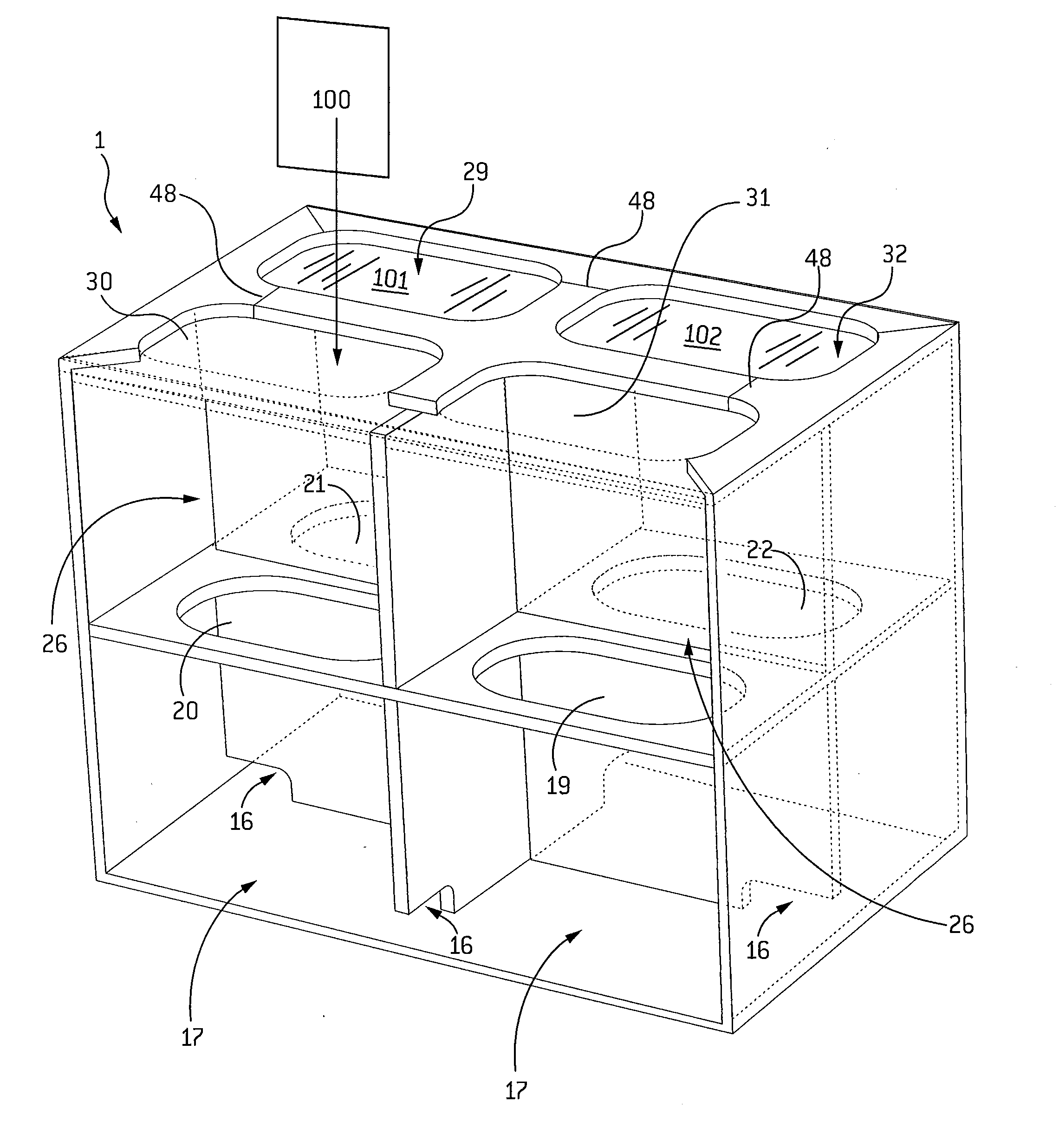
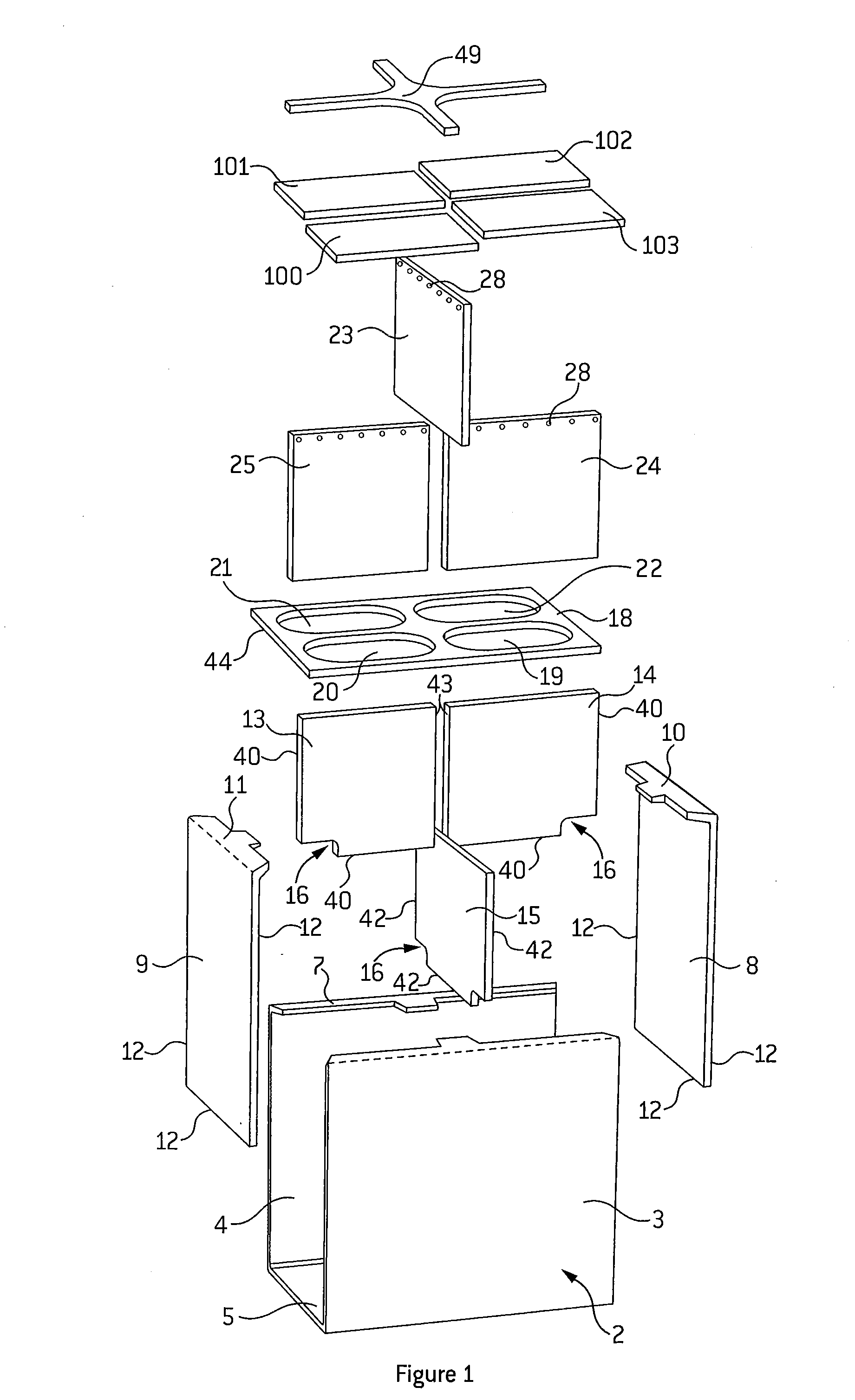
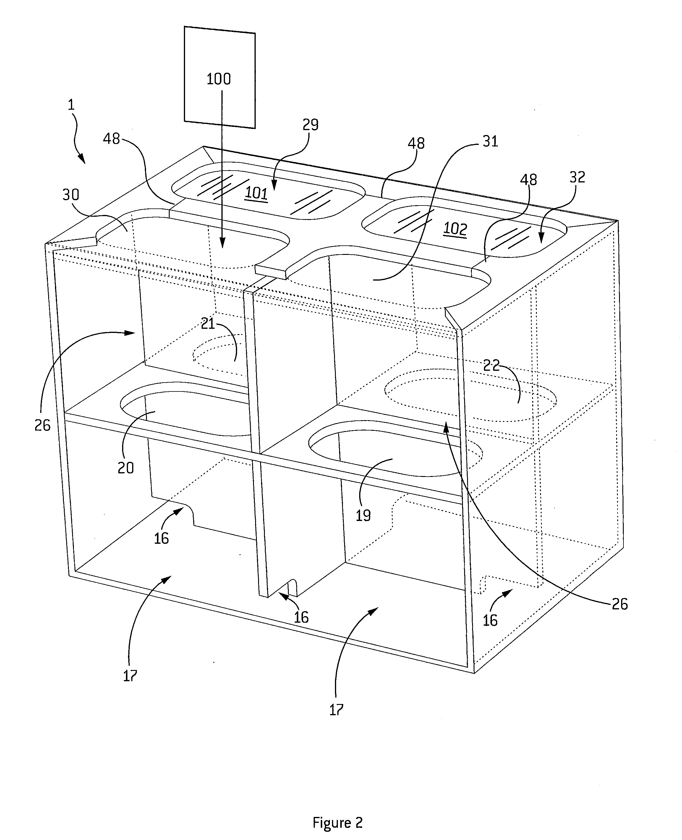
[0125]The following discussion of FIGS. 1 and 2 generally describes the features of the tank (1) in the order in which the tank is constructed.

[0126]The tank (1) is made from copolymer polypropylene.

[0127]A body portion (2) is initially formed by folding sheet material to provide side walls (3 and 4), and a base (5) of a tank (1).

[0128]The body portion (2) is folded to create a first pair of flanges (6 and 7) which extend over the top of the body portion (2).

[0129]End walls (8 and 9) are also formed from sheet material. The end walls (8 and 9) are folded to create a further pair of flanges (10 and 11). The flanges (10 and 11) extend over the newly formed tank (1).

[0130]The end walls (8 and 9) are secured by plastic welding along both the inside and outside edges (12) of the walls (8, 9) to complete the body portion (2).

[0131]Then substantially vertical longitudinal baffles (13 and 14) are positioned in the tank (1) and each side of edges (40) of the baffles (13, 14) is plastic welde...


PUM

PropertyMeasurementUnit
dimensionsaaaaaaaaaa
volumeaaaaaaaaaa
shapeaaaaaaaaaa

Abstract

There is provided a method of constructing a tank which provides an improvement in the strength of the tank. Therefore, tanks can be constructed from thinner materials providing lighter tanks which are more capable of withstanding explosions or other trauma.
In addition, the tank is more suited for use in vehicles as it effectively controls unwanted movement of fluid within the tank.

Description

TECHNICAL FIELD[0001]The present invention relates to methods of constructing tanks for holding liquids, and in particular storage tanks for use in vehicles.BACKGROUND ART[0002]The weight of tanks is often sought to be reduced by making the walls thinner and / or from lighter materials such as plastic sheet. Using lighter / thinner materials however can consequently lead to a decrease in the strength of the tank. The tanks are therefore prone to bulging and deformation when carrying a load.[0003]It would therefore be beneficial to have a tank which has a both strong and light weight construction. Preferably, the tank whilst having relatively thin walls may still provide a robust construction, which is the same, or substantially similar, to that achieved with heavier tanks. In addition, a light weight tank construction which can better withstand damage that would occur from explosive, or other, forces that could cause rupture, would be advantageous.[0004]Many tanks used in vehicles have ...

Claims


Application Information

Patent Timeline
Patent Type & Authority Applications(United States)
IPC IPC(8): B60P3/22B23P19/04B65D6/00B23P17/00B65D88/12
CPCB65D90/52Y10T29/49Y10T29/49826Y10T29/49879B21D51/06B21D51/18
Inventor REA, JAMES ROBERT
Owner REA JAMES ROBERT
Why Eureka
Try Eureka