
Wheel for vehicles and method for producing the same

a technology for vehicles and wheels, applied in the field of wheels, can solve the problems of dimensional stability, flanges fsub>2 /sub>, and the wheel is not dimensionally stable, so as to achieve the effect of increasing the strength of the disk, good material yield, and freedom of design

Inactive Publication Date: 2010-02-25
ZENIYA ARUMINIUMU SEISAKUSHO K
View PDF11 Cites 0 Cited by
  • Summary
  • Abstract
  • Description
  • Claims
  • Application Information

AI Technical Summary

Benefits of technology

"The present invention provides a wheel for a vehicle that has the strongest rim section and the degree of freedom of design. The wheel has an outer rim with a disk section formed by embossing a portion with a large plate thickness and a rim section formed by drawing. The inner rim has flange sections formed by inward curled double shape. The wheel is lightweight and has good material yield. The method for producing the wheel allows for the integration of the outer and inner rims by welding. The wheel eliminates the need for finishing the rim edge and has the advantage of being lightweight."

Problems solved by technology

As opposed to this, the wheel has a disadvantage of being unable to freely design a disk d1 portion since the disk d1 portion is made up of three plates.
As opposed to this, the wheel has a disadvantage that the process of inward curling a flange f2 by roll-molding is difficult and the wheel is thus not dimensionally stabilized.
Further, since its internal stress cannot be held by a process such as drawing, the wheel also has a disadvantage of requiring a rim member with a larger thickness.
Moreover, the wheel also has a disadvantage of being heavy in weight.
As opposed to this, the wheel has a disadvantage that many man-hours are required for processing an outer periphery of the disk d3.
Further, there is no other choice but to scrap all bottom-punched portions in the rim, thus leading to a poor yield.
As opposed to this, the wheel has a disadvantage that the disk d4 portion has insufficient design properties.
Further, the wheel also has a disadvantage that it is not possible to expect weight saving due to increased strength of a thin-plate disk formed by embossing.

Method used


Image

  • Wheel for vehicles and method for producing the same
  • Wheel for vehicles and method for producing the same
  • Wheel for vehicles and method for producing the same

Examples


Embodiment Construction

[0039]The best mode for carrying out the present invention is specifically described based upon FIGS. 1 and 2.

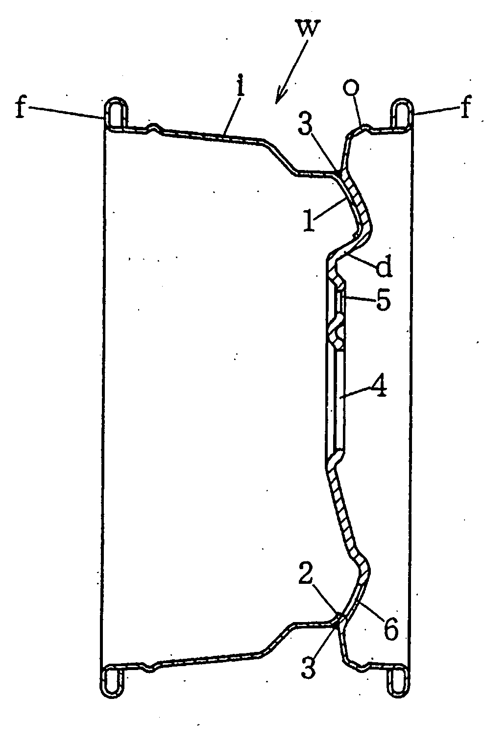
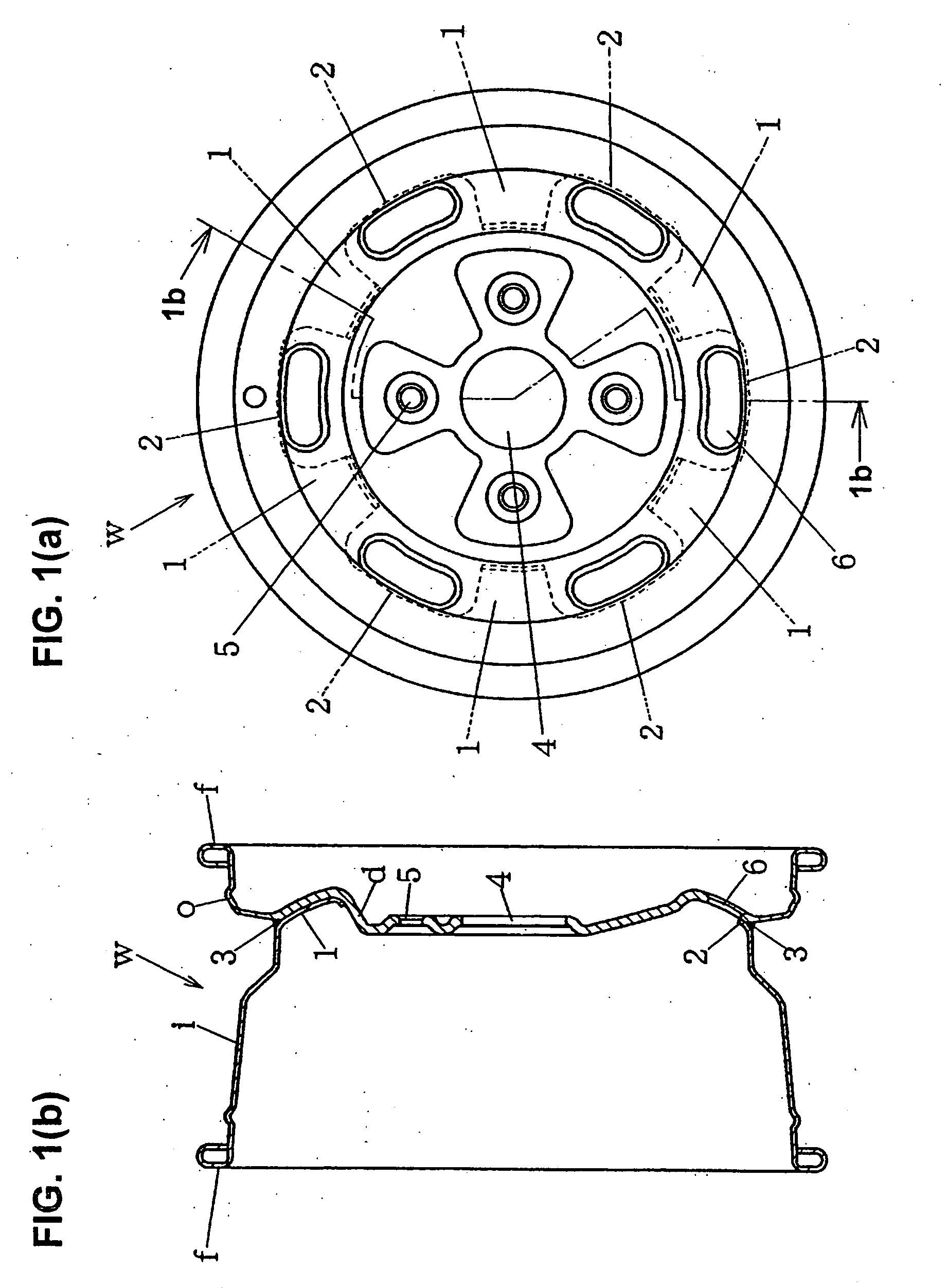
[0040]FIG. 1 shows an example of a wheel w for a vehicle which has an outer rim o including a disk section d formed by embossing a portion with a large plate thickness and a rim section formed by drawing a portion with a small plate thickness as a periphery of the disk section d, out of a material with a plate thickness varied such that a central portion is thick and a periphery thereof is thin.

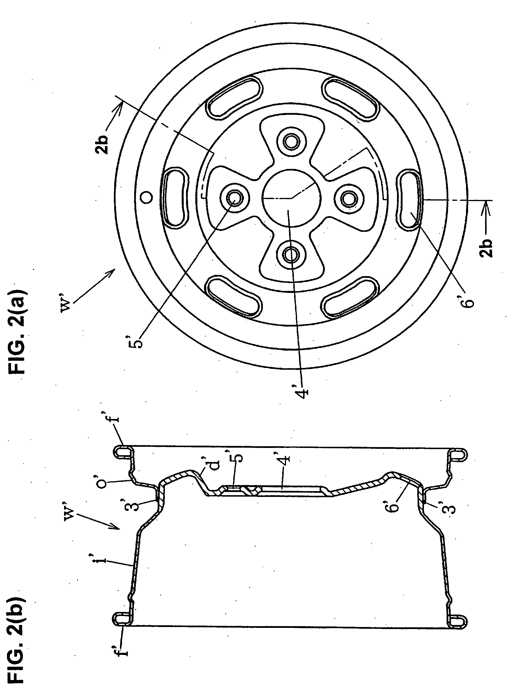
[0041]As opposed to this, FIG. 2 shows another example of a wheel w′ for a vehicle which has an inner rim i′ including a disk section d′ formed by embossing a portion with a large plate thickness and a rim section formed by drawing a portion with a small plate thickness as a periphery of the disk section d′, out of a material with a plate thickness varied such that a central portion is thick and a periphery thereof is thin.

[0042]The wheel w for a vehicle shown in FIG. 1 is comprised o...


PUM

PropertyMeasurementUnit
thicknessaaaaaaaaaa
shapeaaaaaaaaaa
strengthaaaaaaaaaa

Abstract

A wheel for a vehicle including an outer rim and an inner rim, in which the outer rim is comprised of a disk section formed by embossing a first portion having a certain thickness and a rim section formed by drawing a second portion having a smaller thickness than the first portion so as to make a periphery of the disk section; and the inner rim is comprised of superimposed portions formed by drawing and to be superimposed on prescribed positions of the disk section of the outer rim. Flange sections of the outer and inner rims are respectively inwardly curled so as to form a double-layered structure. The outer and inner rims are integrated by welding with the superimposed portions set at the prescribed positions of the disk section.

Description

BACKGROUND OF THE INVENTION[0001]1. Field of the Invention[0002]The present invention relates to a wheel for a variety of vehicles including a vehicle capable of traveling in a place with any terrain (a so-called all terrain vehicle, hereinafter simply referred to as an ATV).[0003]2. Description of the Related Art[0004]Wheels for use in this kind of vehicle are often made of aluminum or an aluminum alloy for the purpose of being made lightweight, and a variety of kinds thereof have been in mass production.[0005]Examples of the most typical wheel among them include a wheel formed in such a manner that, as shown in Japanese Patent Application Laid-Open (Kokai) No. 62-166102 and the like, an inner rim i1 and an outer rim o1 are separately drawn into cup shape, a center plate c1 is inserted between the drawn inner rim i1 and outer rim o1, and the three plates, the inner rim i1, the outer rim o1 and the center plate c1, are simultaneously welded (31) so as to be integrated with one anoth...

Claims


Application Information

Patent Timeline
Patent Type & Authority Applications(United States)
IPC IPC(8): B60B19/00B21K1/38
CPCB21C37/065B21D53/30Y10T29/49526B60B21/104B60B25/004B60B3/02Y02T10/86
Inventor MATSUO, JUNJIAMAKI, KIYOSHISUZUKI, SHOJINISHIZAKA, TAKASHI
Owner ZENIYA ARUMINIUMU SEISAKUSHO K
Learn More