Shape memory alloy actuator system

a technology of shape memory alloy and actuator system, which is applied in the direction of thermal electric motors, electric devices, generators/motors, etc., can solve the problems of excessive heating of wires b>700/b>, deterioration of performance, and inability to maintain shape, so as to prevent excessive heating of wires of shape memory alloy

Inactive Publication Date: 2010-02-25
OLYMPUS CORP
View PDF17 Cites 18 Cited by
  • Summary
  • Abstract
  • Description
  • Claims
  • Application Information

AI Technical Summary

Benefits of technology

[0011]The present invention is made in view of the abovementioned circumstances, for making it possible to prevent an excessive heating of a shape memory alloy wire in a shape memory alloy actuator system in which a moving distance of a mobile object is determined in advance by a regulating member. Concretely, an object

Problems solved by technology

However, when a shape memory alloy is heated excessively, characteristics as a shape memory alloy cease to be exerted favorably.
In spite of this, when an attempt is made to carry out a control even when the actuator is in a state of not being capable of moving, by a regulating member, the performance is deteriorated by heating the wire 700 excessive

Method used


Image

  • Shape memory alloy actuator system
  • Shape memory alloy actuator system
  • Shape memory alloy actuator system

Examples


Embodiment Construction

[0029]An embodiment of a shape memory alloy actuator system according to the present invention will be described below in detail by referring to the accompanying diagrams. However, the present invention is not restricted by the embodiment described below.

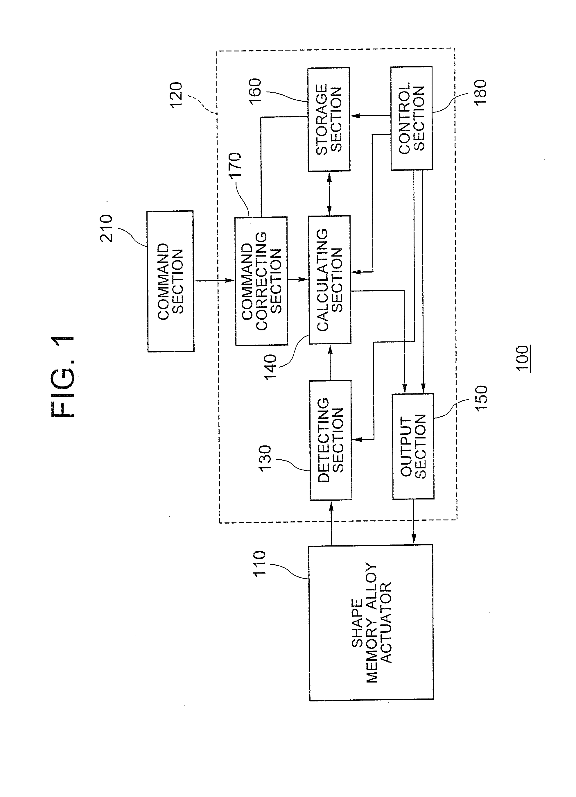
[0030]FIG. 1 is a block diagram showing a structure of a shape memory alloy actuator system 100 according to the embodiment of the present invention. As shown in FIG. 1, the shape memory alloy actuator system 100 includes a shape memory alloy actuator 110 and a resistance feedback circuit 120.

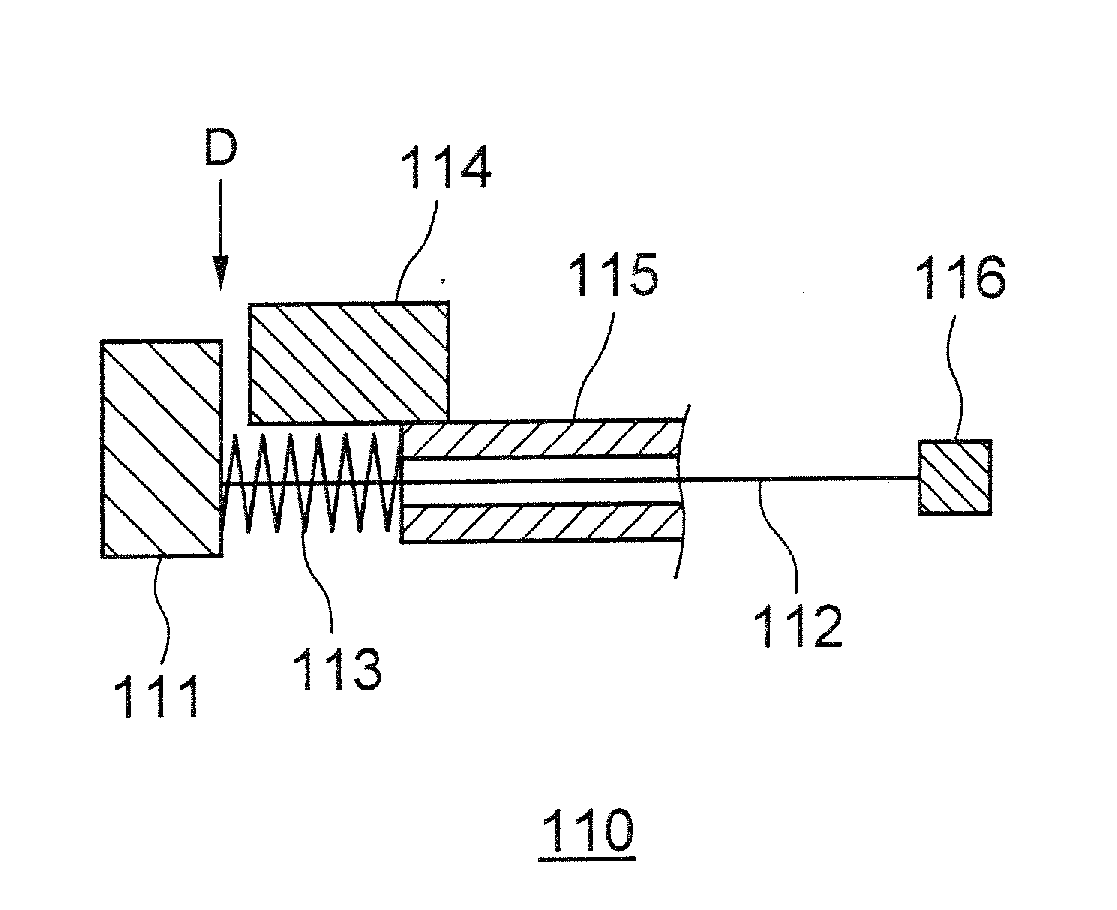
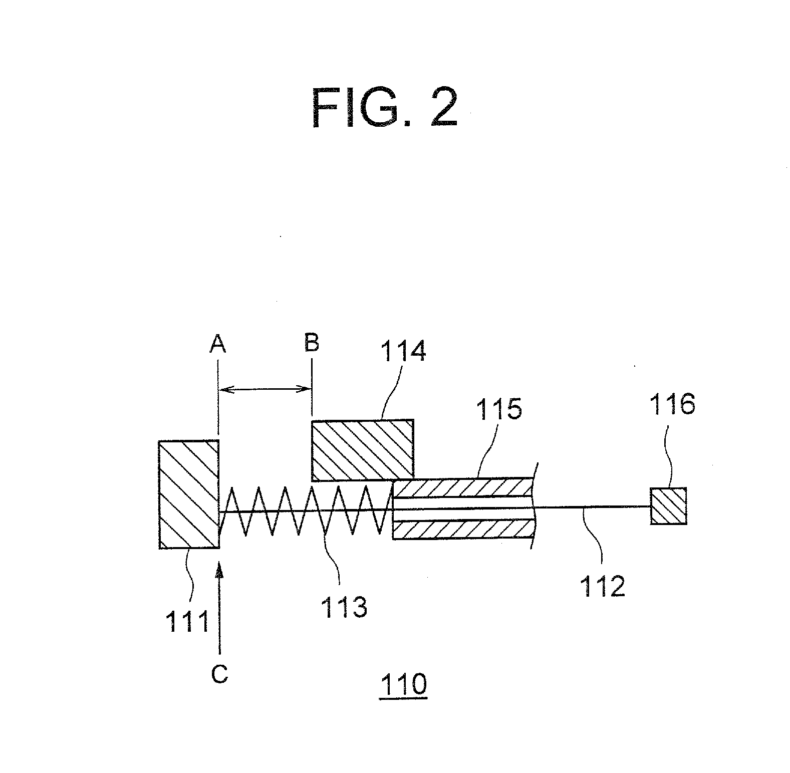
[0031]FIG. 2 is a diagram showing a schematic structure of the shape memory alloy actuator 110, as well as an extended state of a shape memory alloy wire 112. FIG. 3 is a diagram showing a schematic structure of the shape memory alloy actuator 110, as well as is a diagram showing a state in which the shape memory alloy wire 112 is contracted upon being heated, and also being controlled by using the resistance feedback circuit 120.

[0032]The shap...


PUM


Abstract

A resistance feedback circuit has a detecting section which detects a resistance of a shape memory alloy wire at the time of contraction and elongation, a calculating section which compares an output signal acquired from the detecting section and a signal input by a command section, and calculates an applied electric current corresponding to the resistance value detected, an output section which outputs the applied electric current which is output from the calculating section, to the shape memory alloy actuator, a control section which controls the detecting section, the calculating section and the output section, a storage section which stores a maximum value and a minimum value of the resistance which is measured in advance, and a command correcting section which corrects a signal output from the command section, based on the resistance value stored in the storage section, and a command signal which is output from the command correcting section is set to a resistance value which is higher than the minimum resistance value by a correction value.

Description

CROSS-REFERENCE TO RELATED APPLICATION[0001]The present application is based upon and claims the benefit of priority from the prior Japanese Patent Application No. 2008-211457 filed on Aug. 20, 2008; the entire contents of which are incorporated herein by reference.BACKGROUND OF THE INVENTION[0002]1. Field of the Invention[0003]The present invention relates to a shape memory alloy actuator system.[0004]2. Description of the Related Art[0005]In a shape memory alloy, a shape of the shape memory alloy is changed by passing an electric power, and by controlling universally an expansion and a contraction of the shape memory alloy while detecting a value of an electrical resistance which changes with the change in the shape of the shape memory alloy, it is possible to control a degree of expansion and contraction of the shape memory alloy. Therefore, the shape memory alloy has a characteristic which is extremely suitable for small-sizing of an apparatus.[0006]However, when a shape memory ...

Claims


Application Information

Patent Timeline
IPC IPC(8): H02N10/00
CPCF03G7/065
Inventor MATSUKI, KAORU
Owner OLYMPUS CORP
Why Eureka
Try Eureka