

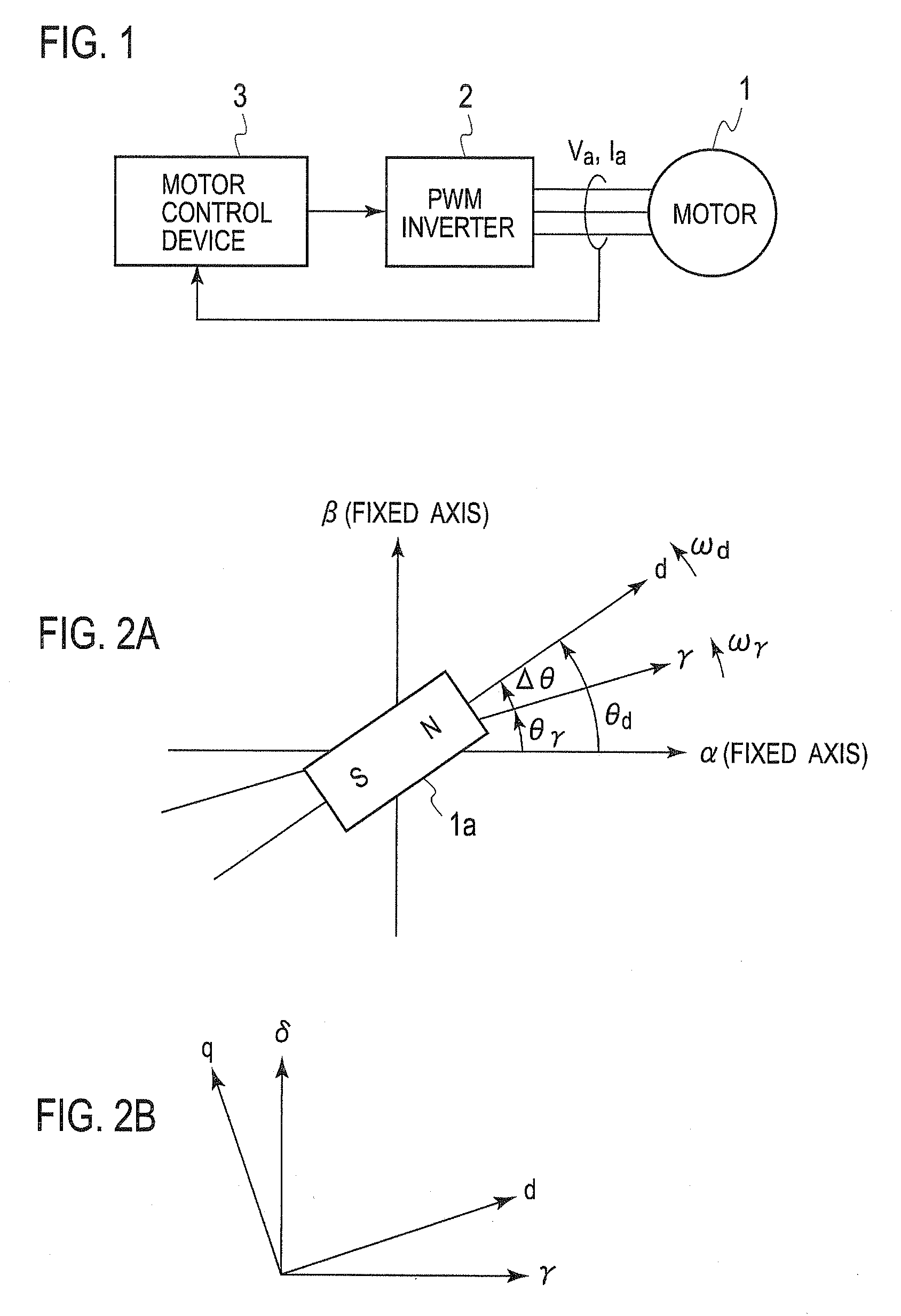
Motor Control Device
a technology of motor control and control device, which is applied in the direction of motor/generator/converter stopper, dynamo-electric gear control, motor/generator/converter stopper, etc., can solve the problems of delay in starting the equipment in which the motor is installed, take about that much time to start the motor as well, etc., and achieve the effect of stably estimating the magnetic pole position and short tim
- Summary
- Abstract
- Description
- Claims
- Application Information
AI Technical Summary
Benefits of technology
Problems solved by technology
Method used
Image

Examples
first embodiment
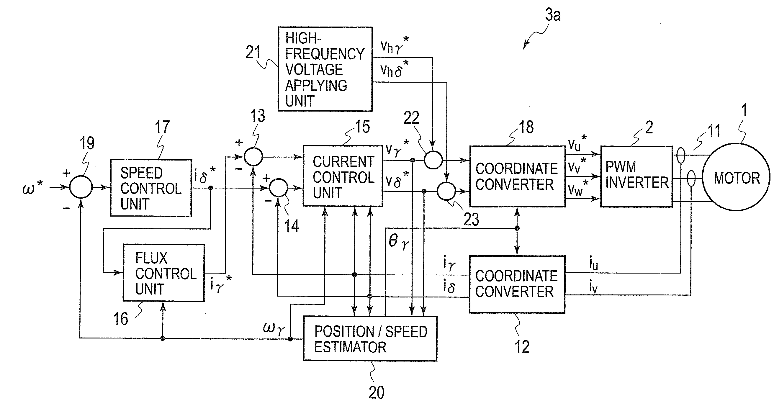
[0123]Now, a first embodiment of the invention will be described. FIG. 13 is a block diagram of a motor drive system according to the first embodiment. The motor drive system of FIG. 13 includes the motor 1 and the inverter 2 of FIG. 1, as well as a motor control device 3a and a phase current sensor 11. The motor control device 3a may be utilized as the motor control device 3 of FIG. 1. The motor control device 3a includes each unit referred to by reference numbers 12 to 23. It also may be considered that the phase current sensor 11 is included in the motor control device 3a. Each unit within the motor control device 3a can freely utilize each value generated within the motor control device 3a.
[0124]Each unit that constitutes the motor drive system of this embodiment and each of the embodiments described below updates command values (such as vγ*, vd*, iγ*, id*) and state quantities (such as iu, iv, iγ, id, θγ and ωγ) that it computes (or detects) and outputs at a predetermined upda...
second embodiment
[0147]Now, a second embodiment of the invention will be explained. FIG. 16 is an internal block diagram of a motor drive system according to the second embodiment. The motor drive system of FIG. 16 includes the motor 1 and the inverter 2 of FIG. 1, as well as a motor control device 3b and the phase current sensor 11. The motor control device 3b may be utilized as the motor control device 3 of FIG. 1. The motor control device 3b includes each unit referred to by reference numbers 12b, 13 to 17, 18b, 19, 20b, and 21b. It also may be considered that the phase current sensor 11 is included in the motor control device 3b. Each unit within the motor control device 3b can utilize freely each value generated within the motor control device 3b.
[0148]Similarly to the first embodiment, the motor control device 3b performs a vector control of the motor 1 such that the axial error Δθ converges to zero. Therefore, in the second embodiment, the γ-axis, which is an estimated axis for control, is m...
third embodiment
[0163]Now, a third embodiment of the invention will be described. FIG. 18 is a block diagram of a motor drive system according to the third embodiment. The motor drive system of FIG. 18 includes the motor 1 and the inverter 2 of FIG. 1, as well as a motor control device 3c and the phase current sensor 11. The motor control device 3c may be utilized as the motor control device 3 of FIG. 1. The motor control device 3c includes each unit referred to by reference numbers 112 to 121. It also may be considered that the phase current sensor 11 is included in the motor control device 3c. Each unit within the motor control device 3c can utilize freely each value generated within the motor control device 3c.
[0164]Unlike in the first and second embodiments, the motor control device 3c estimates the magnetic pole position directly without making the axial error Δθ converge to zero.
[0165]The position / speed estimator 120 computes the phase θd representing the magnetic pole position (that is, est...
PUM
 Abstract
Description
Claims
Application Information