
Charging apparatus and charging method

Inactive Publication Date: 2010-02-25
SONY CORP
View PDF3 Cites 31 Cited by
  • Summary
  • Abstract
  • Description
  • Claims
  • Application Information

AI Technical Summary

Benefits of technology

[0014]According to the embodiments of the present invention, batteries can be charged efficiently in view of power consumption.

Problems solved by technology

The electric power is uselessly consumed at the time of charging due to the heat generation.

Method used


Image

  • Charging apparatus and charging method
  • Charging apparatus and charging method
  • Charging apparatus and charging method

Examples


Embodiment Construction

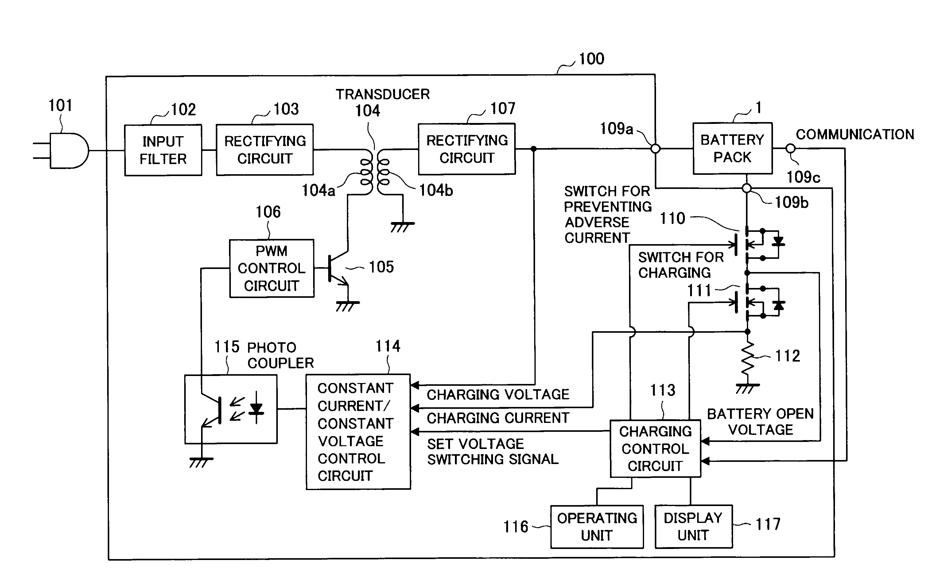
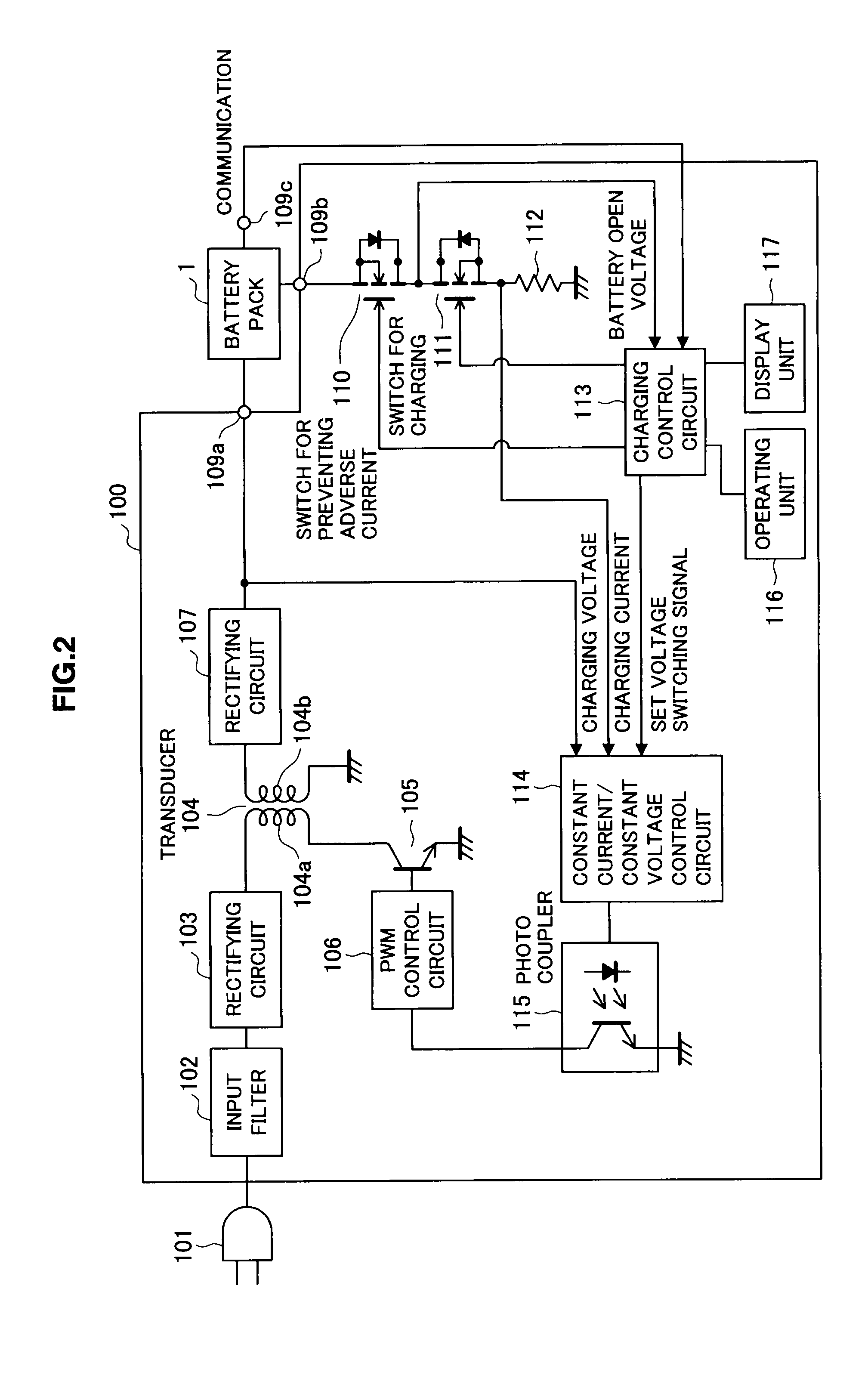
[0025]Hereinafter, preferred embodiments of the present invention will be described in detail with reference to the appended drawings. Note that, in this specification and the appended drawings, structural elements that have substantially the same function and structure are denoted with the same reference numerals, and repeated explanation of these structural elements is omitted.

[0026](Configuration of Battery Pack)

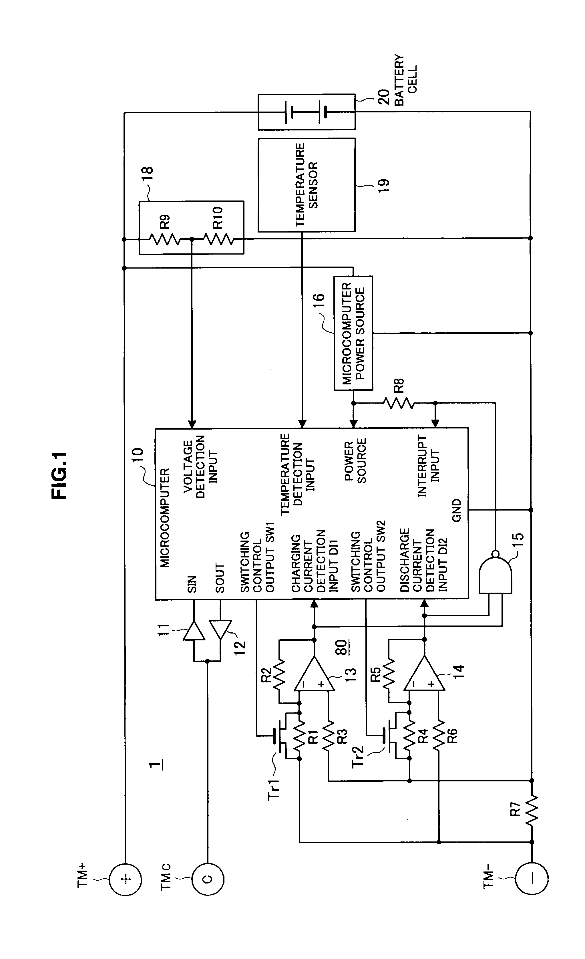
[0027]A configuration of a battery pack according to one embodiment of the present invention is described. FIG. 1 is a circuit diagram illustrating the configuration of the battery pack according to the embodiment of the present invention.

[0028]A battery cell 20 is, for example, a lithium ion secondary battery. The battery pack 1 according to the embodiment shown in FIG. 1 has the battery cell 20 which is charged and discharged, a current detecting unit 80 and a microcomputer 10. The current detecting unit 80 detects a charging / discharging current i [mA] of the battery ce...


PUM


Abstract

The present invention provides a charging apparatus capable of efficiently charging battery in view of power consumption and a charging method. The charging apparatus has a charging unit which charges a battery, a remaining capacity detecting unit which detects remaining capacity of the battery, a necessary charging capacity obtaining unit which obtains charging capacity necessary for use after completion of the charging of the battery, an additional charging capacity calculating unit which calculates additional charging capacity for additionally charging the battery based on the remaining capacity and the necessary charging capacity of the battery, a charging current determining unit which determines a charging current at the time when the charging unit charges for the additional charging capacity based on power consumption generated at the time of charging for the additional charging capacity, and a control unit which controls the charging unit based on the determined charging current.

Description

BACKGROUND OF THE INVENTION[0001]1. Field of the Invention[0002]The present invention relates to a charging apparatus and a charging method.[0003]2. Description of the Related Art[0004]In related art, battery packs including secondary battery such as lithium ion battery, NiCd battery or nickel hydride battery are publicly known.[0005]The publicly-known battery packs have a microcomputer which calculates a remaining battery capacity and communicates with an electronic device using a battery as a power source, a peripheral circuit of the microcomputer and a circuit for detecting a state of a battery cell for calculating the remaining battery capacity by means of the microcomputer. Japanese Patent Application Laid-Open No. 9-247864 discloses a technique which detects a remaining capacity of a battery cell based on a current integrating amount at the time of charging / discharging when a remaining capacity of the battery cell is calculated.SUMMARY OF THE INVENTION[0006]In recent years, an...

Claims


Application Information

Patent Timeline
IPC IPC(8): H02J7/00
CPCH02J7/025Y02B40/90H02J7/041H02J7/027Y10S903/903Y10S903/907Y10S903/904H02J7/0071H02J7/02Y02B40/00H02J50/10H02J7/0047H02J5/00
Inventor NAGASHIMA, OSAMUTASHIRO, KEIMIYAJIMA, YOICHITAKESHITA, TOSHIO
Owner SONY CORP
Learn More