Planar polarization splitter

a polarization splitter and planar technology, applied in the field of polarization splitters, can solve the problems of reducing the insertion loss of the design, affecting the insertion efficiency of the design, and unable to provide such wavelength insensitivity in the low-cost and compact design of the apparatus

Active Publication Date: 2010-02-25
RPX CORP
View PDF9 Cites 32 Cited by
  • Summary
  • Abstract
  • Description
  • Claims
  • Application Information

AI Technical Summary

Problems solved by technology

Providing such wavelength insensitivity in a low-cost and compact designed apparatus has been problematic, however.
In addition to requiring additional processing steps, such designs can have substantial insertion losses.

Method used


Image

  • Planar polarization splitter
  • Planar polarization splitter
  • Planar polarization splitter

Examples


Embodiment Construction

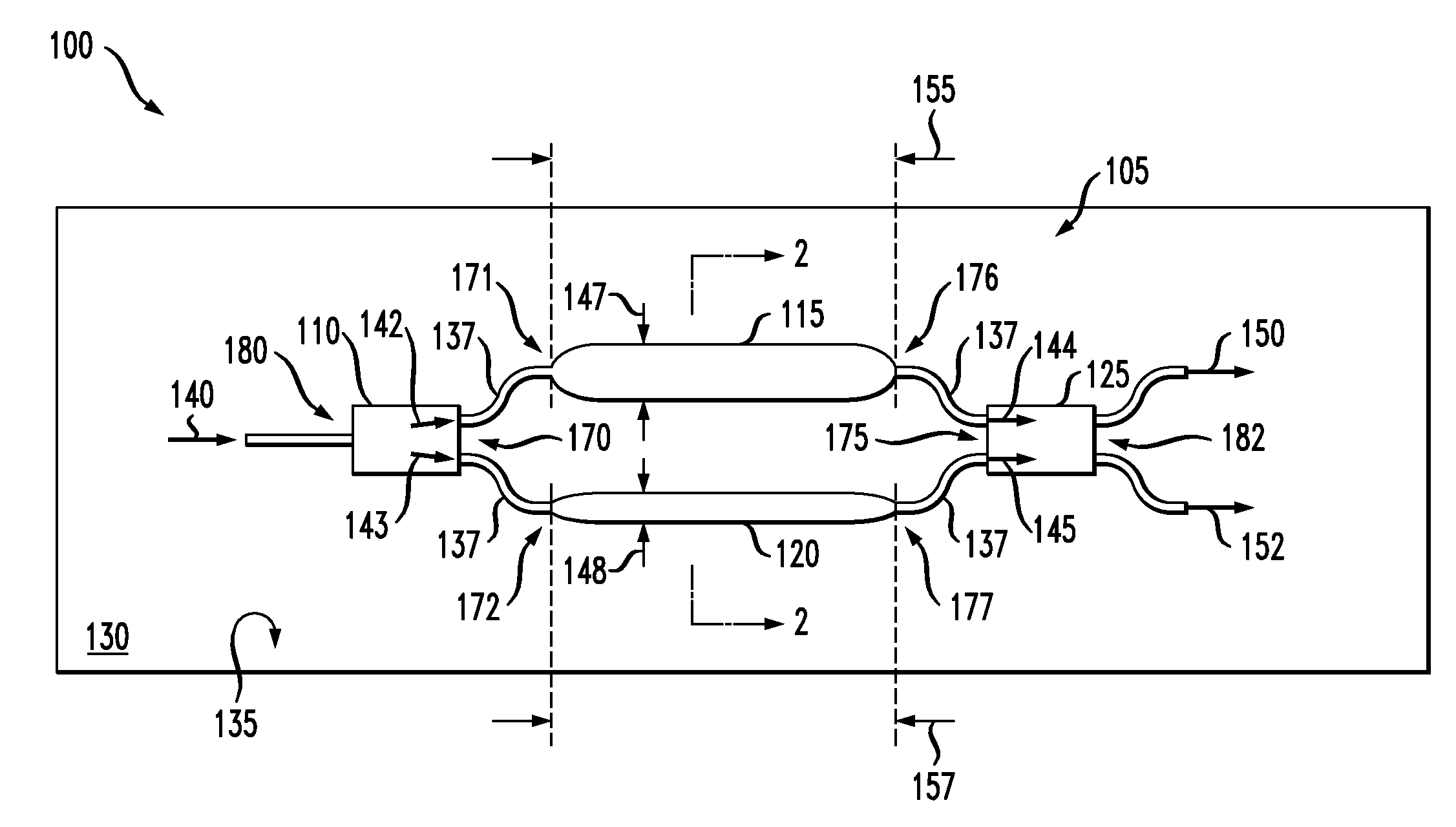
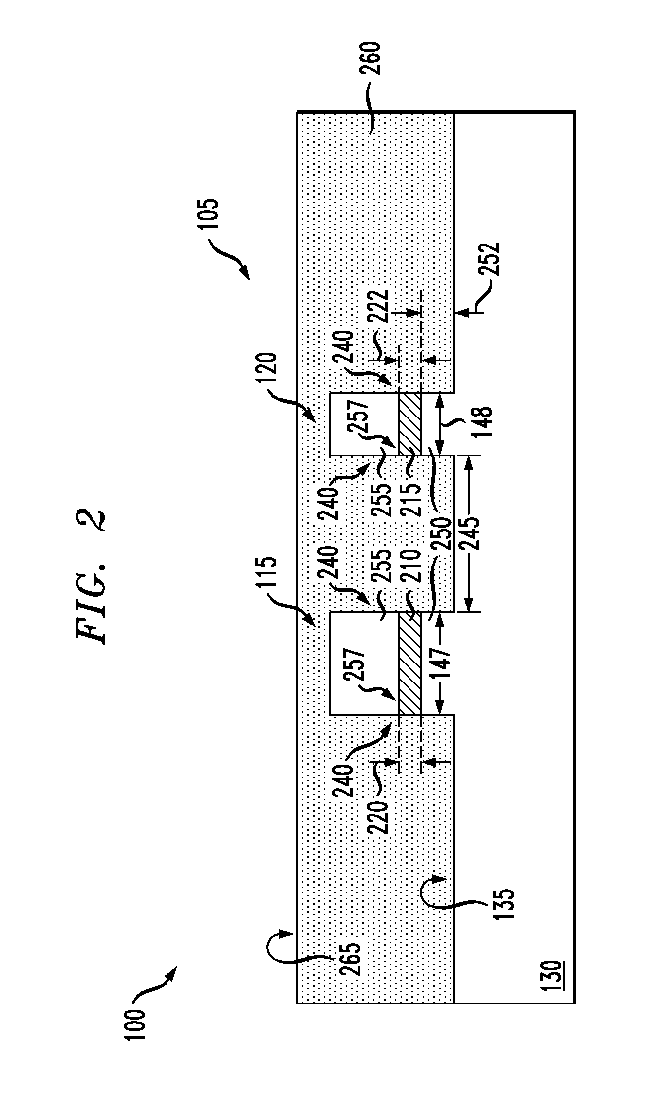
[0014]It was discovered that changing the width in two ridge waveguides can in itself cause sufficient changes in the effective refractive indexes of TM and TE polarized light so as to provide a desired phase shift over reasonably short propagation distances. A 180-degree phase differences between the accumulated phase difference between TE and TM light between the two waveguides can be implemented for compact polarization splitter designs by placing the two waveguides in an interferometer. For instance, for short planar waveguide lengths (e.g., less than about 500 microns) two waveguide cores having appropriately different widths can provide 180-degree phase shifts in the TE or TM light output between the two waveguides.

[0015]In a polarization splitting application of such a structure, the 180-degree phase-shifted light can be passed through a coupler to provide two outputs: one output that is substantially TE polarized light and another output that is substantially TM polarized li...


PUM


Abstract

An apparatus comprising a planar optical structure that includes an input coupler, first and second planar waveguides and an output coupler, all on a planar substrate. The input coupler is configured to divide an incoming light into two input light beams. Each of the first and second waveguides is configured to receive one of the two input light beams. The first waveguide has a first core with a width that is greater than a width of a second core of the second waveguide. At least one of the first or second planar waveguides is birefringent. The output coupler is configured to receive the light beams after passage through the first and second waveguides. A first output light beam from the output coupler is substantially TE polarized light and a second output light beam from the output coupler is substantially TM polarized light.

Description

CO-PENDING RELATED PATENT APPLICATION[0001]The present patent application is related to a concurrently filed patent application entitled, “MONOLITHIC COHERENT OPTICAL DETECTORS” to Y. K. Chen, et al., Ser. No. ______, filed on Aug. 19, 2008 which is commonly assigned with the present application and incorporated by reference in its entirety.TECHNICAL FIELD OF THE INVENTION[0002]The present disclosure is directed, in general, to polarization splitters, and, methods using and of manufacturing thereof.BACKGROUND OF THE INVENTION[0003]This section introduces aspects that may be helpful to facilitating a better understanding of the inventions. Accordingly, the statements of this section are to be read in this light. The statements of this section are not to be understood as admissions about what is in the prior art or what is not in the prior art.[0004]Polarization splitters split polarized light into transverse electric (TE) and transverse magnetic (TM) polarized light. Mach-Zehnder int...

Claims


Application Information

Patent Timeline
Patent Type & Authority Applications(United States)
IPC IPC(8): G02B6/26
CPCG02B6/105G02B6/126G02B2006/12154G02B2006/12116G02B2006/12097G02B6/27G02B6/12
Inventor DOERR, CHRISTOPHER RICHARD
Owner RPX CORP
Why Eureka
Try Eureka