
Microfabricated elastomeric valve and pump systems

a technology of elastomeric valves and micro-elastomeric materials, applied in the direction of lift valves, multi-way valves, chemical vapor deposition coatings, etc., can solve the problems of large and complex designs, limited bulk and surface micro-machining methods, and each of these approaches suffers from its own limitations

Inactive Publication Date: 2005-05-26
CALIFORNIA INST OF TECH
View PDF99 Cites 86 Cited by
  • Summary
  • Abstract
  • Description
  • Claims
  • Application Information

AI Technical Summary

Benefits of technology

[0009] Advantages of fabricating the present structures by binding together layers of soft elastomeric materials include the fact that the resulting devices are reduced by more than two orders of magnitude in size as compared to silicon-based devices. Further advantages of rapid prototyping, ease of fabrication, and biocompatability are also achieved.
[0014] An advantage of patterning moderate sized features (> / =10 microns) using a photoresist method is that a high resolution transparency film can be used as a contact mask. This allows a single researcher to design, print, pattern the mold, and create a new set of cast elastomer devices, typically all within 24 hours.
[0015] A further advantage of either above embodiment of the present invention is that due to its monolithic or integral nature, (i.e., all the layers are composed of the same material) is that interlayer adhesion failures and thermal stress problems are completely avoided.
[0016] Further advantages of the present invention's preferred use of a silicone rubber or elastomer such as RTV 615 manufactured by General Electric, is that it is transparent to visible light, making a multilayer optical trains possible, thereby allowing optical interrogation of various channels or chambers in the microfluidic device. As appropriately shaped elastomer layers can serve as lenses and optical elements, bonding of layers allows the creation of multilayer optical trains. In addition, GE RTV 615 elastomer is biocompatible. Being soft, closed valves form a good seal even if there are small particulates in the flow channel. Silicone rubber is also bio-compatible and inexpensive, especially when compared with a single crystal silicon.
[0019] Further advantages of the present pumps and valves are that their small size makes them fast and their softness contributes to making them durable. Moreover, as they close linearly with differential applied pressure, this linear relationship allows fluid metering and valve closing in spite of high back pressures.
[0027] In other optional preferred aspects, magnetic or conductive materials can be added to make layers of the elastomer magnetic or electrically conducting, thus enabling the creation of all elastomer electromagnetic devices.

Problems solved by technology

Unfortunately, each of these approaches suffers from its own limitations.
A limitation of the first approach of silicon-based micro-machining is that the stiffness of the semiconductor materials used necessitates high actuation forces, which in turn result in large and complex designs.
In fact, both bulk and surface micro-machining methods are limited by the stiffness of the materials used.
In addition, adhesion between various layers of the fabricated device is also a problem.
On the other hand, when surface micro-machining, thermal stresses between the various layers of the device limits the total device thickness, often to approximately 20 microns.

Method used


Image

  • Microfabricated elastomeric valve and pump systems
  • Microfabricated elastomeric valve and pump systems
  • Microfabricated elastomeric valve and pump systems

Examples


Embodiment Construction

[0095] The present invention comprises a variety of microfabricated elastomeric structures which may be used as pumps or valves. Methods of fabricating the preferred elastomeric structures are also set forth.

[0096] Methods of Fabricating the Present Invention:

[0097] Two exemplary methods of fabricating the present invention are provided herein. It is to be understood that the present invention is not limited to fabrication by one or the other of these methods. Rather, other suitable methods of fabricating the present microstructures, including modifying the present methods, are also contemplated.

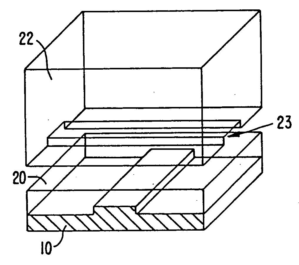
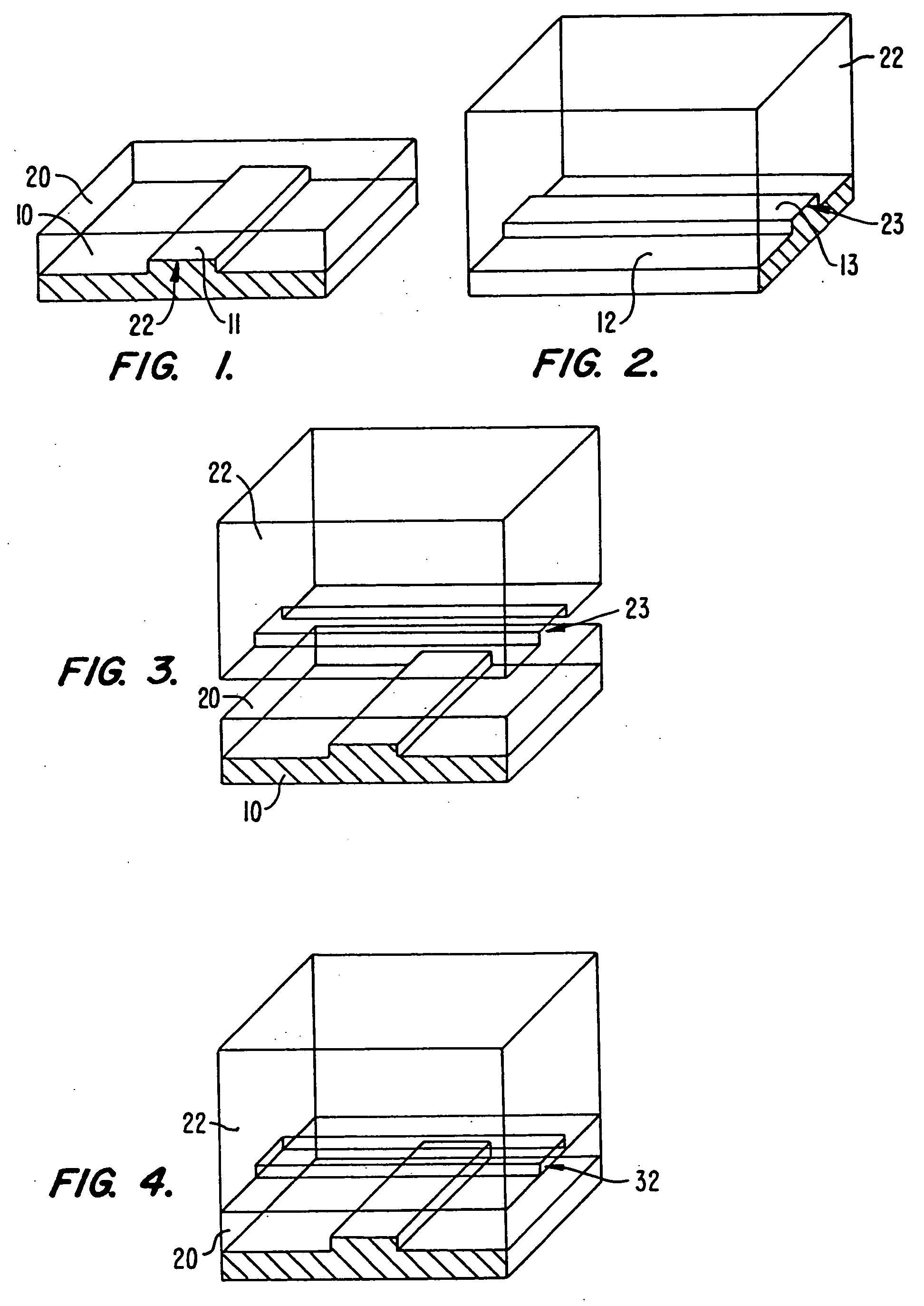
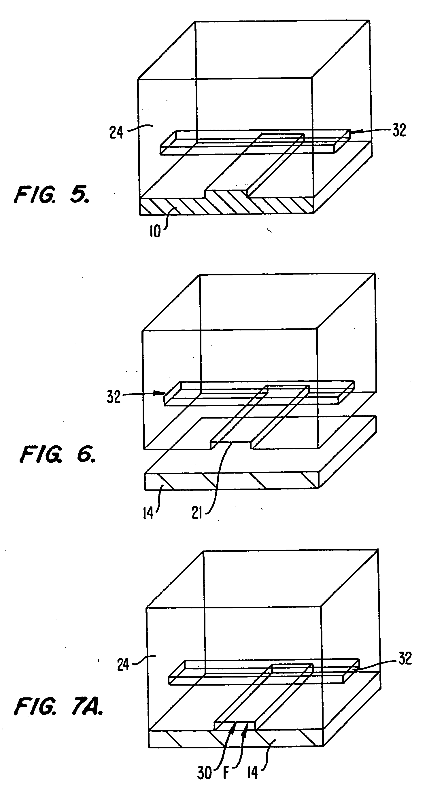
[0098] FIGS. 1 to 7B illustrate sequential steps of a first preferred method of fabricating the present microstructure, (which may be used as a pump or valve). FIGS. 8 to 18 illustrate sequential steps of a second preferred method of fabricating the present microstructure, (which also may be used as a pump or valve).

[0099] As will be explained, the preferred method of FIGS. 1 to 7B invol...


PUM

PropertyMeasurementUnit
Elastomericaaaaaaaaaa
Ratioaaaaaaaaaa
Electrical conductoraaaaaaaaaa

Abstract

A method of fabricating an elastomeric structure, comprising: forming a first elastomeric layer on top of a first micromachined mold, the first micromachined mold having a first raised protrusion which forms a first recess extending along a bottom surface of the first elastomeric layer; forming a second elastomeric layer on top of a second micromachined mold, the second micromachined mold having a second raised protrusion which forms a second recess extending along a bottom surface of the second elastomeric layer; bonding the bottom surface of the second elastomeric layer onto a top surface of the first elastomeric layer such that a control channel forms in the second recess between the first and second elastomeric layers; and positioning the first elastomeric layer on top of a planar substrate such that a flow channel forms in the first recess between the first elastomeric layer and the planar substrate.

Description

CROSS-REFERENCES TO RELATED APPLICATIONS [0001] This is a continuation of U.S. nonprovisional patent application Ser. No. 09 / 605,520 filed Jun. 27, 2000. This nonprovisional patent application also claims the benefit of the following previously filed U.S. provisional patent application Ser. No. 60 / 186,856 filed Mar. 3, 2000. The text of these prior patent applications is hereby incorporated by reference. The text of concurrently filed PCT Application No. PCT / US00 / 17740 filed Jun. 27, 2000 is also hereby incorporated by reference.STATEMENT AS TO RIGHTS TO INVENTIONS MADE UNDER FEDERALLY SPONSORED RESEARCH AND DEVELOPMENT [0002] Work described herein has been supported, in part, by National Institute of Health grant HG-01642-02. The United States Government may therefore have certain rights in the invention.TECHNICAL FIELD [0003] The present invention relates to microfabricated structures and methods for producing microfabricated structures, and to microfabricated systems for regulati...

Claims


Application Information

Patent Timeline
IPC IPC(8): B01L3/00B81B1/00G03F7/20B81B3/00B81B7/00B81C1/00B81C99/00C12Q1/68F04B17/00F04B35/04F04B43/04F15C5/00F16K7/00F16K17/02F16K99/00
CPCB01L3/502707Y10T428/24744B01L3/502738B01L2300/0861B01L2300/0887B01L2300/123B01L2400/046B01L2400/0481B01L2400/0655B81B2201/036B81B2201/054B81C1/00119B81C2201/019B81C2201/034C12Q1/6874F04B43/043F15C5/00F16K99/0001F16K99/0015F16K99/0046F16K99/0048F16K99/0051F16K99/0059F16K2099/0074F16K2099/0076F16K2099/0078F16K2099/008F16K2099/0094B01L3/50273Y10T156/10F16K13/00Y10T428/24479C12Q2535/125Y10T137/0491Y10T137/0497Y10T137/2224Y10T137/87249B33Y80/00Y10T137/87981F04B43/14B81B7/00F16K11/20F15C1/06F16K31/126B81B5/00B29C51/00F16K1/20
Inventor UNGER, MARC A.CHOU, HOU-PUTHORSEN, TODD A.SCHERER, AXELQUAKE, STEPHEN R.
Owner CALIFORNIA INST OF TECH
Learn More