
Apparatus and method for employing miniature inertial measurement units for deducing forces and moments on bodies

a technology of inertial measurement and apparatus, applied in the direction of turn-sensitive devices, golf clubs, instruments, etc., can solve the problems of difficulty in directly measuring the net joint forces and moments, collectively referred to as joint kinetics

Inactive Publication Date: 2013-03-21
RGT UNIV OF MICHIGAN
View PDF9 Cites 83 Cited by
  • Summary
  • Abstract
  • Description
  • Claims
  • Application Information

AI Technical Summary

Benefits of technology

The patent text describes a method for capturing human motion using a markerless system. This method uses passive vision systems to capture human motion and a computer model to determine the kinematics of individual body segments. The system employs a simplified sensor design that reduces the effect of skin movement error on marker positioning. The sensor design uses a three axis accelerometer and does not require an angular rate gyros, which makes it less expensive. The method provides accurate measures of the rev rate and axis point, which can be useful in various applications such as sports equipment design and gait analysis.

Problems solved by technology

Unfortunately, in the case of human or animal analysis, without invasive surgery, it is very difficult to directly measure the net joint forces and moments which are collectively referred to as the joint kinetics.

Method used


Image

  • Apparatus and method for employing miniature inertial measurement units for deducing forces and moments on bodies
  • Apparatus and method for employing miniature inertial measurement units for deducing forces and moments on bodies
  • Apparatus and method for employing miniature inertial measurement units for deducing forces and moments on bodies

Examples


Embodiment Construction

[0029]Example embodiments will now be described more fully with reference to the accompanying drawings. Example embodiments are provided so that this disclosure will be thorough, and will fully convey the scope to those who are skilled in the art. Numerous specific details are set forth such as examples of specific components, devices, and methods, to provide a thorough understanding of embodiments of the present disclosure. It will be apparent to those skilled in the art that specific details need not be employed, that example embodiments may be embodied in many different forms and that neither should be construed to limit the scope of the disclosure. In some embodiments, aspects and / or features of recited embodiments can be combined into additional embodiments not specifically recited herein.

[0030]The terminology used herein is for the purpose of describing particular example embodiments only and is not intended to be limiting. As used herein, the singular forms “a”, “an” and “the...


PUM


Abstract

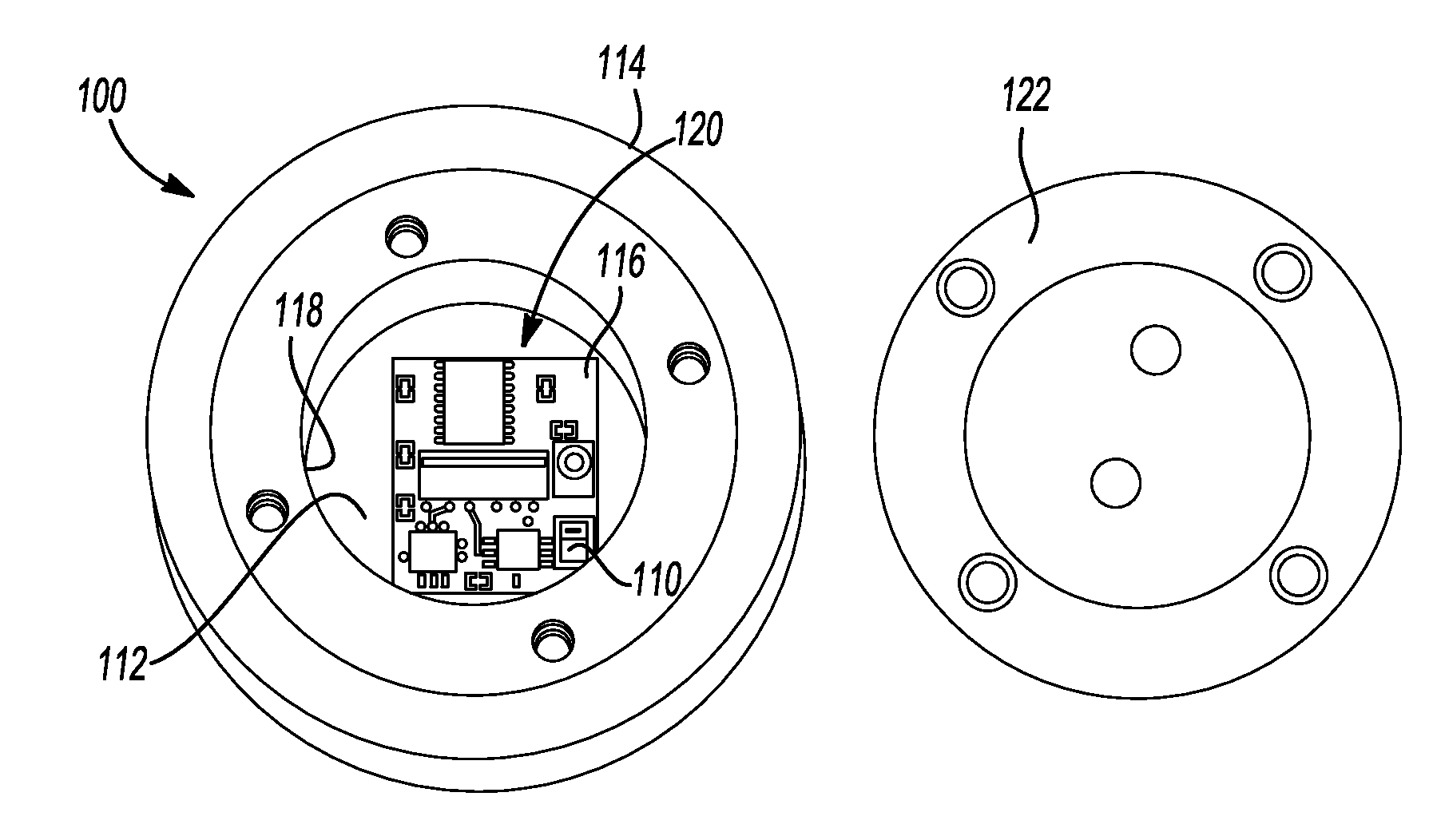
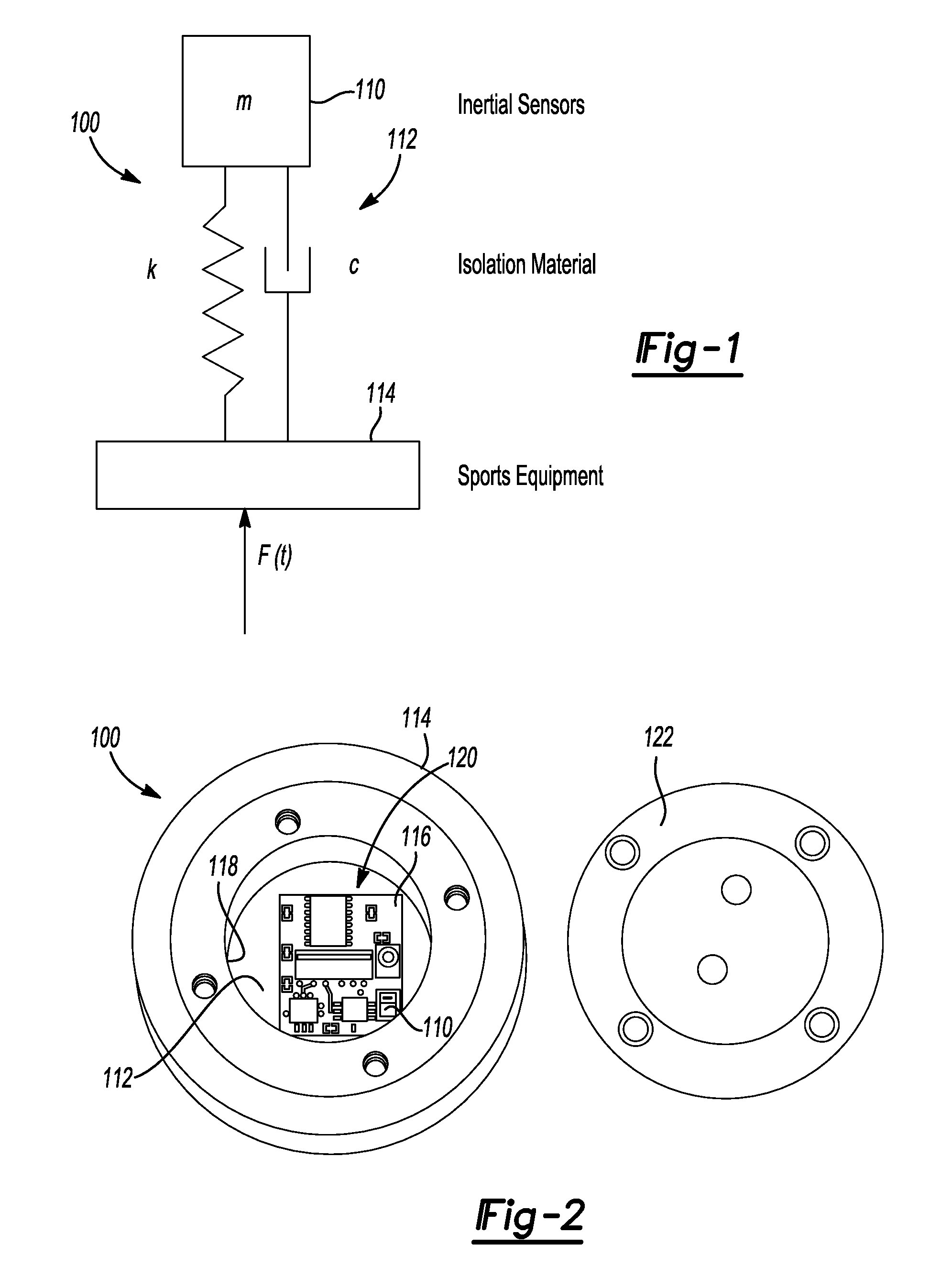
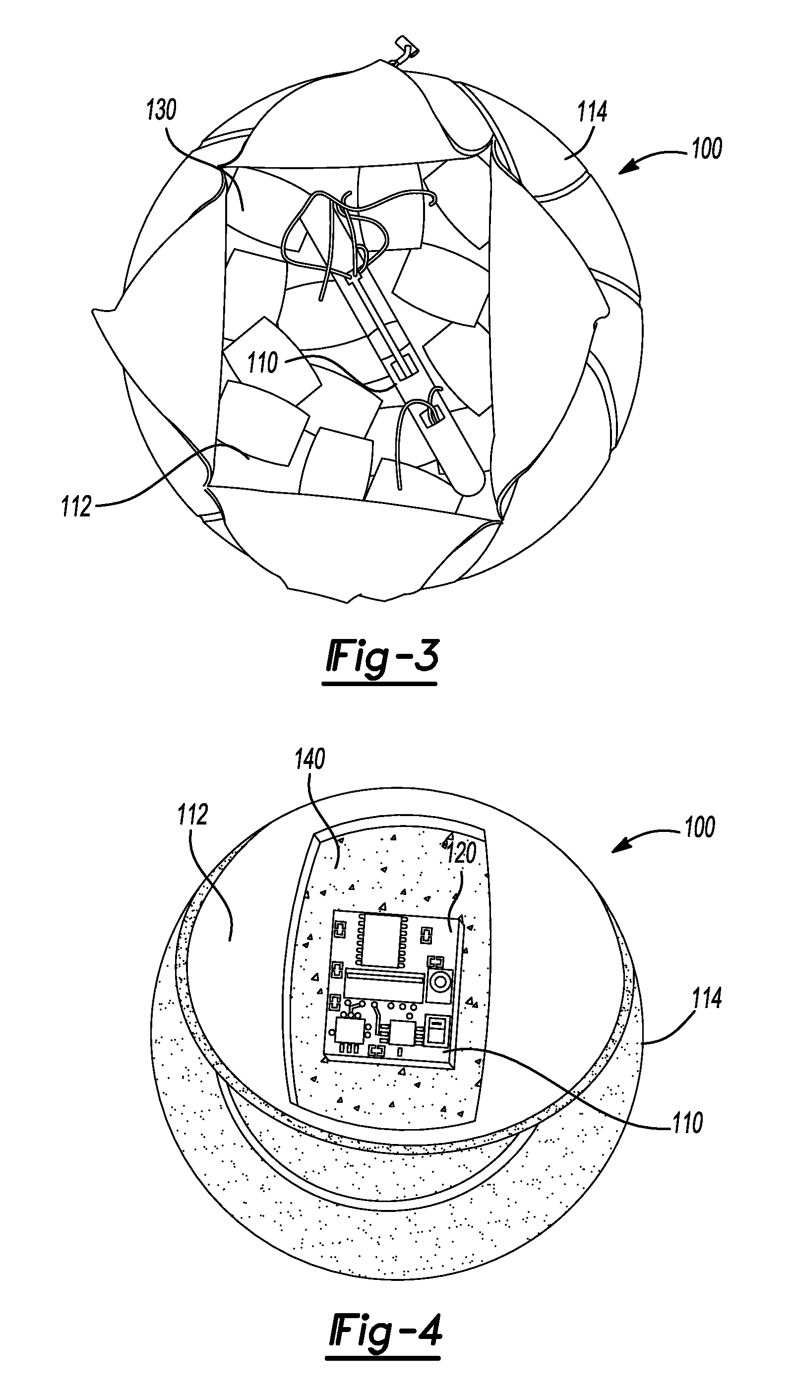
An apparatus for analyzing movement of equipment. The apparatus includes an inertial measurement unit continuously measuring six rigid body degrees of freedom of the equipment and outputting data representative thereof, wherein the inertial measurement unit defines a planar substrate having a single common plane. The inertial measurement unit further includes at least one angular rate gyro and at least one accelerometer sufficient to measure the six rigid body degrees of freedom and each being mounted on the single common plane. The apparatus further includes a processing unit determining the acceleration of the mass center of the equipment, the angular velocity and the angular acceleration of the equipment through a single derivative operation.

Description

FIELD[0001]The present disclosure relates to apparatus and methods for deducing forces and moments on bodies and, more particularly, to apparatus and methods for deducing forces and moments on bodies using only a single derivative operation.BACKGROUND AND SUMMARY[0002]This section provides background information related to the present disclosure which is not necessarily prior art. This section also provides a general summary of the disclosure, and is not a comprehensive disclosure of its full scope or all of its features.[0003]Often in the analysis of movement of a body there is a need to determine the net forces and moments acting on the body. Whether it be during gait analysis of a human or animal, during the analysis of the throwing motion of baseball pitchers or the impact of sports equipment, or even during rehabilitation from injury or surgery, researchers can benefit from knowing the net loads that are placed on a subject's joints, body portions, or the equipment being used. ...

Claims


Application Information

Patent Timeline
IPC IPC(8): G06F15/00
CPCG01P15/00A63B2243/0095A61B5/6828A61B5/6831A61B5/6895A61B5/7239A61B5/742A61B5/1114A61B5/112A61B5/1122A61B5/4528A61B2503/10A61B2505/09A61B2562/0219A63B59/06A63B65/02A63B65/10A63B67/14A63B69/0026A63B37/0001A63B37/0003A63B39/00A63B41/00A63B43/00A63B53/14A63B59/0014A63B59/0033A63B2220/30A63B2220/34A63B2220/833A63B2225/50A63B2243/0008G01C19/56A63B60/10A63B60/16A63B60/06A63B60/08A63B2102/18A63B59/50A63B2102/182A63B60/46
Inventor PERKINS, NOELMCGINNIS, RYANKING, KEVIN
Owner RGT UNIV OF MICHIGAN
Learn More