Shift control system and method

a technology of shift control and control system, applied in the direction of automatic initiation, braking system, transportation and packaging, etc., can solve problems such as vibration, and achieve the effect of reducing the possibility of the driver being struck

Inactive Publication Date: 2010-02-25
TOYOTA JIDOSHA KK
View PDF4 Cites 22 Cited by
  • Summary
  • Abstract
  • Description
  • Claims
  • Application Information

AI Technical Summary

Benefits of technology

[0007]The invention provides a shift control system that reduces the possibility that the driver feel uncomfortable when he or she operates a P switch while the vehicle is coming to a stop.
[0009]According to the shift control system described above, when the driver inputs a request for switching the shift range to the P range despite that the vehicle has not yet stopped completely, the wheel cylinder pressure is maintained at the hold pressure, rather than switching the shift range to the P range immediately. At this time, more specifically, the wheel cylinder pressure is maintained for the hold duration and then the shift range is switched to the P range. This procedure ensures that the lock mechanism is actuated when the vehicle is in a stable state, and this eliminates or reduces the possibility of rocking of the vehicle which may make the driver feel unconformable.
[0012]The above-described shift control system may further include a stop state determination portion that determines, based on the behavior of the vehicle, whether the vehicle has stopped, and the hold duration may be set to a time period until the stop state determination portion determines that the vehicle has stopped. That is, in this case, the hold duration is not fixed, but it is variably set in accordance with the state of the vehicle. As such, the control can be more precisely performed based on the stop state of the vehicle, and it is possible to prevent the wheel cylinder pressure from becoming higher than necessary.
[0015]The hold duration may be set such that the larger the deceleration of the vehicle at a given time point immediately before the vehicle stops, the shorter the hold duration. That is, the larger the deceleration of the vehicle immediately before the vehicle stops, the shorter the time period to when the vehicle stops. Therefore, it is desirable to set the hold duration appropriately in consideration of the stability and quickness in switching the shift range to the P range.
[0016]Further, after switching the shift range to the parking range, the shift control portion may cause the brake control portion to reduce the wheel cylinder pressure gradually from the hold pressure. If the wheel cylinder pressure is reduced from the hold pressure at a given gradient, the shocks on the vehicle are suppressed, and therefore the vehicle can be stopped in a more stable manner.
[0017]Accordingly, the shift control system of the invention eliminates or reduces the possibility that the driver feel uncomfortable when he or she operates the P switch while the vehicle is coming to a stop.

Problems solved by technology

In this case, the rotating output shaft is forcibly locked by the lock mechanism, and the resultant reaction force causes the vehicle to rock, making the driver feel uncomfortable, and moreover, vibrations occur due to backlashes at the gears of the power transfer mechanism.

Method used


Image

  • Shift control system and method
  • Shift control system and method
  • Shift control system and method

Examples


Embodiment Construction

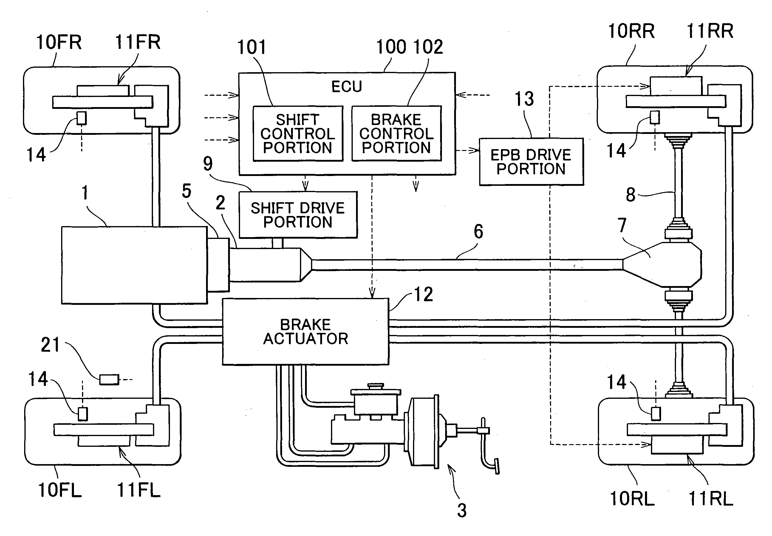
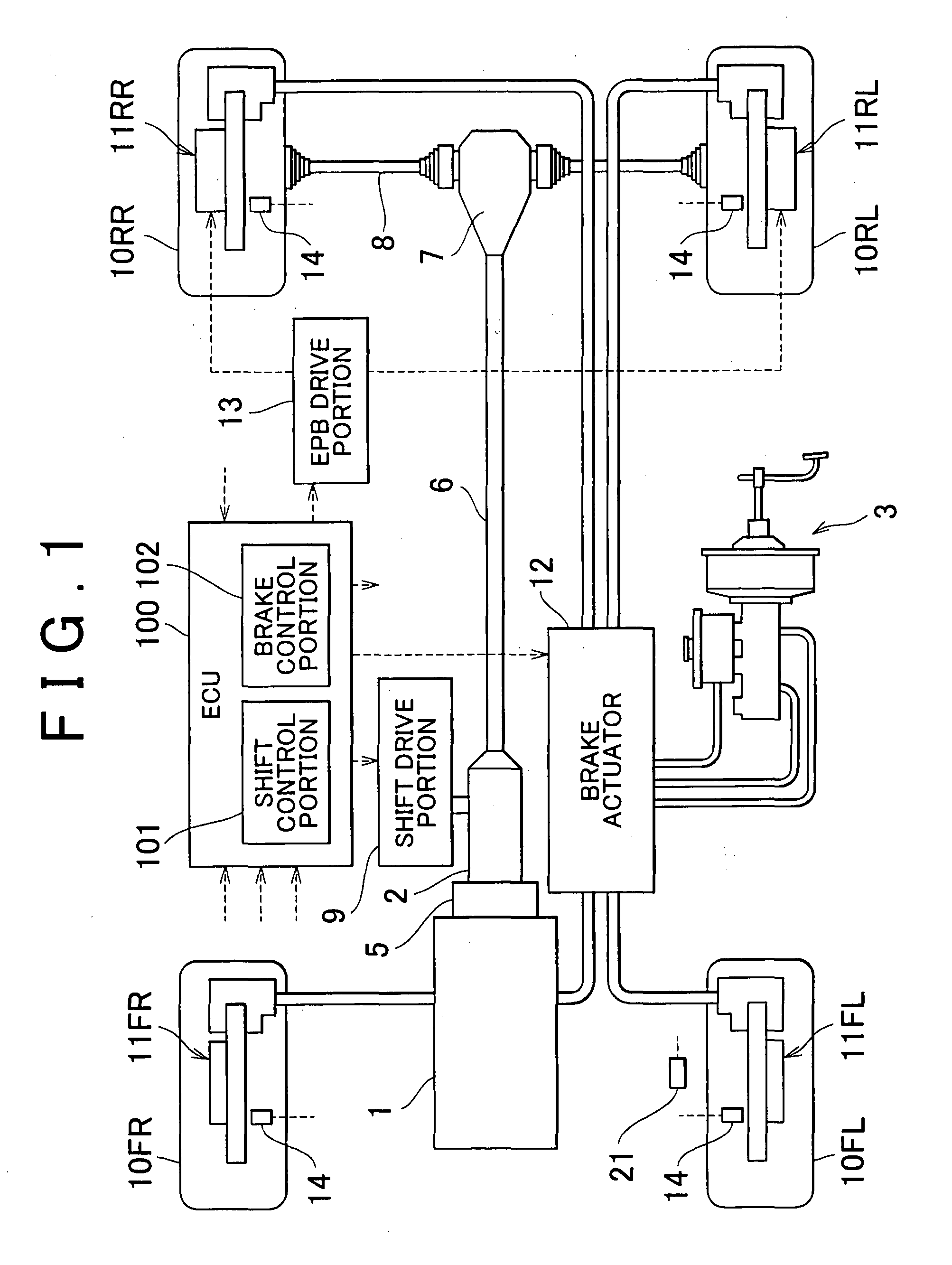
[0026]Hereinafter, example embodiments of the invention will be described in detail with reference to the drawings. FIG. 1 is a view showing the overall configuration of a shift control system according to an example embodiment of the invention.

[0027]Referring to FIG. 1, the vehicle of this example embodiment has an engine 1 that serves as a source of drive power for the drive wheels of the vehicle, an automatic transmission 2 that transmits the drive power at a given speed ratio, a steering unit that steers the wheels of the vehicle (not shown in the drawings), a brake system 3 that applies braking forces to the respective wheels of the vehicle, various electronic control units (will be referred to as “ECUs”) that control the respective components, etc. The vehicle of this example embodiment is a rear-drive vehicle, and the drive power of the engine 1 is transferred to the rear wheels via a torque converter 5, the automatic transmission 2, a propeller shaft 6, a differential 7, axl...


PUM


Abstract

When the driver makes a request for switching the shift range to the P range despite that the vehicle has not yet stopped completely, the wheel cylinder pressure is maintained at a brake hold pressure Ph for a while, rather than switching the shift range to the P range immediately. At this time, more specifically, the wheel cylinder pressure is maintained at the brake hold pressure Ph for a brake hold duration Δt within which the vehicle is estimated to stop, and when the brake hold duration Δt has passed, the shift range is switched to the P range. After the lock mechanism is actuated to establish the P range, the wheel cylinder pressure is gradually reduced from the brake hold pressure Ph at a given pressure reducing gradient.

Description

BACKGROUND OF THE INVENTION[0001]1. Field of the Invention[0002]The invention relates to a shift control system for vehicles and in particular to a shift control system for changing the shift range of an automatic transmission in response to shift operation by the driver.[0003]2. Description of the Related Art[0004]In general, a shift lever to be operated by a driver is provided in vehicles with an automatic transmission. As the driver slides the shift lever, a shift range corresponding to the position of the shift lever is selected, whereby the power transfer state of the geared power transfer mechanism of the automatic transmission is changed accordingly. Shifting the shift lever to the parking position corresponding to the parking range (will be referred to as “P range”) activates a lock mechanism to hold a parking gear formed integrally on the output shaft of the power transfer mechanism, whereby the output shaft is locked and thus the vehicle is maintained in a stopped state.[0...

Claims


Application Information

Patent Timeline
Patent Type & Authority Applications(United States)
IPC IPC(8): B60W10/18B60T1/06B60T7/12B60T8/00
CPCB60T7/085B60T7/12B60W10/10B60W10/184B60W30/181B60W30/18109Y10T477/648B60W2520/105B60W2540/12F16H63/486Y10T477/644Y10T477/6388B60W2510/186B60T8/4081
Inventor YAMAMOTO, TAKAYUKI
Owner TOYOTA JIDOSHA KK
Why Eureka
Try Eureka