Leg prosthesis

a technology for prosthesis and legs, applied in the field of leg prosthesis, can solve the problems of shortening the life of the prosthesis and the difficulty of the user to adapt the prosthesis, and achieve the effects of increasing the rotational resistance, increasing the force building up, and increasing the for

Inactive Publication Date: 2010-02-25
INLIEU
View PDF3 Cites 9 Cited by
  • Summary
  • Abstract
  • Description
  • Claims
  • Application Information

AI Technical Summary

Benefits of technology

[0017]An important advantage of the invention is that the activation needed to initiate the height control can, if desired, be done without direct hand operation, as a valve can be opened upon a single press with the healthy foot.
[0018]It is a favorable feature of the invention to provide a compact embodiment and a safe function.
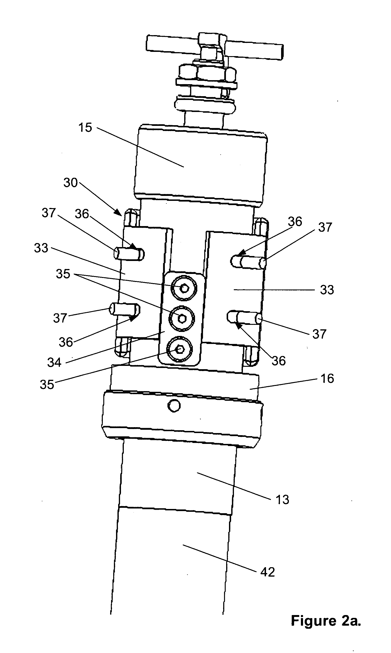
[0019]The leg prosthesis is further provided with means for rotational movement, comprising a torsion device arranged in a cavity provided between the outer tube and the inner tube. In the cavity between the outer and inner tube is arranged an upper bearing at the upper part of the inner tube, and an end cap including a lower bearing and scraper is arranged at the lower part of the inner tube. The upper bearing and the end cap are held in place by the outer tube.
[0020]The torsion device preferably includes only one elastomer which is fixed to the outer tube by means of an elastomer mounting. The elastomer is preferably supported by elastomer supports arranged on the outer tube at both sides adjacent to the elastomer, which elastomer supports are preferably limited in movement in the transversal direction by the elastomer support including slits extending in transversal direction, via which slits the elastomer supports are mounted onto pins extending perpendicularly from the outer tube, inwards against the inner tube. The slits have a limited extension to provide the necessary movement for the pre-stressing of the elastomer at the point of mounting. Further

Problems solved by technology

By using several elastomers, there are disadvantages of a shorter lifetime and

Method used


Image

  • Leg prosthesis
  • Leg prosthesis
  • Leg prosthesis

Examples


Embodiment Construction

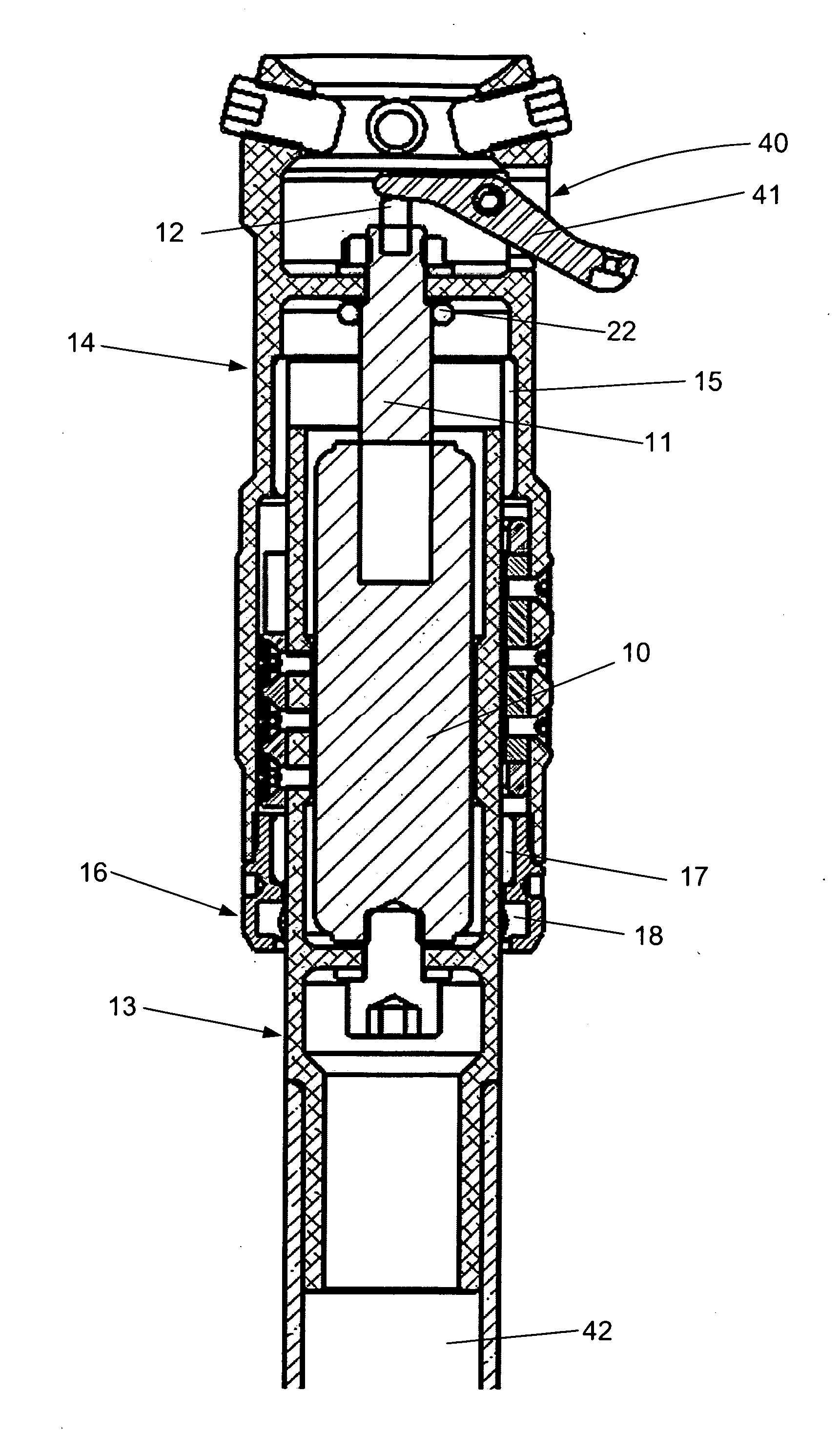
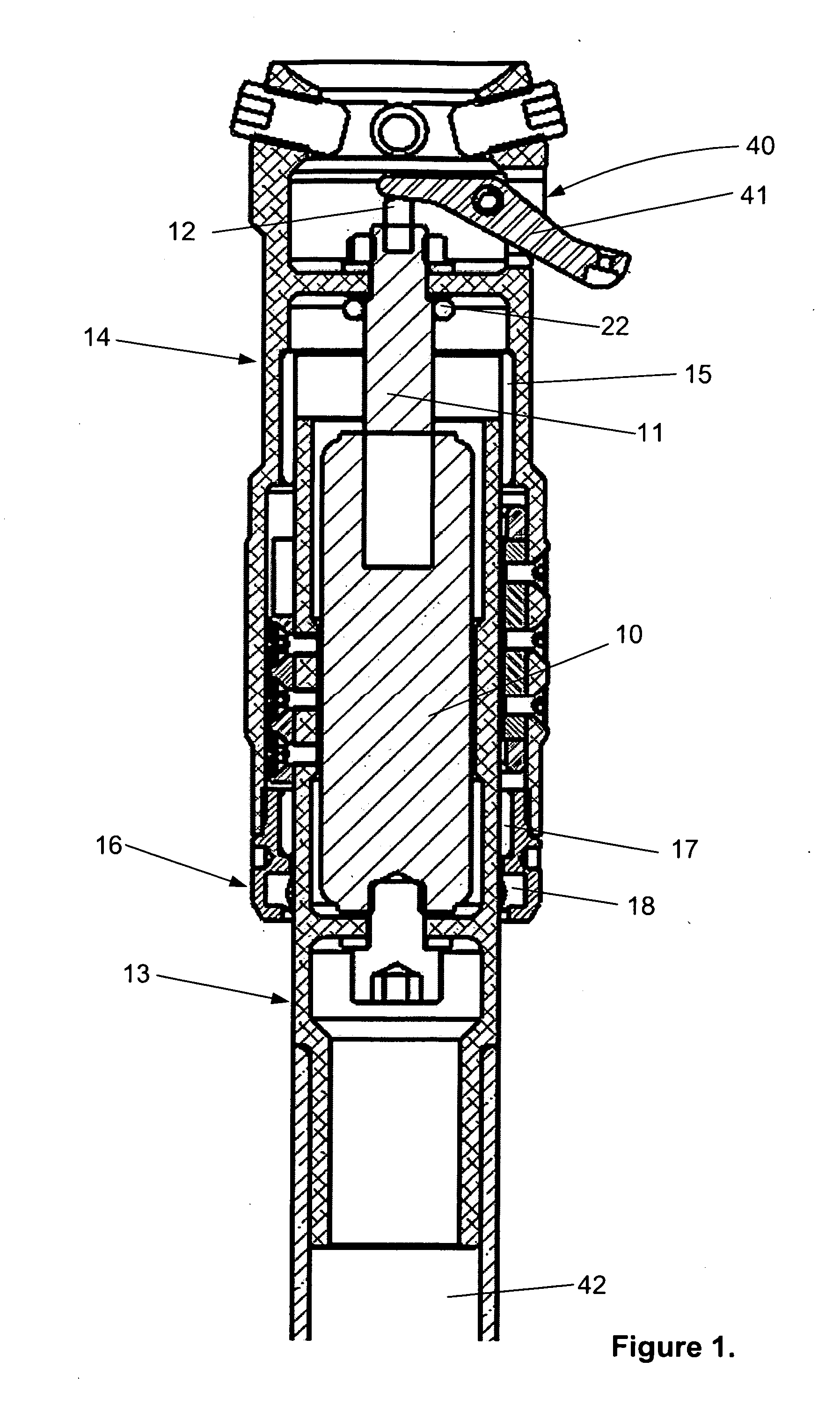
[0032]The device according to FIG. 1 comprises a cylinder 10 with a piston (not shown), which piston has a piston rod 11, which is led vertically upwards through the upper end wall of the cylinder 10. A suitable gas, e.g. nitrogen, is filled into the cylinder 10, on both sides of the piston.

[0033]To make the neutral or rest-position of the piston adjustable, a valve (not shown) is provided, with connections to both sides of the piston. The valve is normally closed, but can be opened via spring tension with an activation lever 12, which is led through the piston rod 11.

[0034]The lower end of the cylinder 10 is fixed to an inner tube 13, which inner tube 13 is adapted for this at its lower part.

[0035]Correspondingly, the piston rod 11 is fixed to an outer tube 14.

[0036]The inner telescopic tube 13 overlaps in all possible positions of the gas spring with the outer telescopic tube 14. The telescopic tubes 13 and 14 may be made of plastic, especially plastic reinforced with carbon fiber...


PUM


Abstract

Leg prosthesis including a cylinder with a piston and a piston rod, the piston rod being led out of one end of the cylinder and attached to an outer tube of the prosthesis, with the lower part of the cylinder being attached to an inner tube of the prosthesis. The outer tube and the inner tube may be connected to parts of the leg prosthesis, and the cylinder may contain a pneumatic or hydraulic medium. The inner tube and the outer tube provide a cavity for the arrangement of a torsion device, where the outer tube can rotate in both directions in relation to the inner tube and vice versa. The torsion device includes an elastomer fixed to the outer tube, elastomer supports fixed to the outer tube and an elastomer end stop fixed to the inner tube.

Description

FIELD OF THE INVENTION [0001]The invention relates to a torsion device for a prosthesis, especially a leg prosthesis.DESCRIPTION OF RELATED ART[0002]Following amputation of a leg, at the calf, knee, thigh or hip, a patient often receives a prosthesis as a substitute for the lost body part. The stump of the patient is generally connected to the prosthesis by a sleeve, known as a “bit-sleeve”. It is also possible to connect the prosthesis directly to the body part with a titanium screw, so-called osseointegration or tissue-integrated prosthesis. The bit-sleeve is provided with an adaptor and an ankle connected to a foot piece. This kind of leg prosthesis may also comprise a knee and a hip, depending on the amputation level.[0003]Shock absorbers are inserted in the prosthesis, cushioning and attenuating the ground reaction forces, which affect the body during walking, running and jumping. Cushioning and attenuation of this load on the sensitive stump and body can help to reduce stump p...

Claims


Application Information

Patent Timeline
IPC IPC(8): A61F2/74A61F2/72
CPCA61F2/60A61F2002/7655A61F2002/5006A61F2002/5007A61F2002/502A61F2002/5032A61F2002/5033A61F2002/5036A61F2002/5072A61F2002/5083A61F2002/5084A61F2002/707A61F2002/745A61F2002/747A61F2002/748A61F2002/7635A61F2/76A61F2/74A61F2/748
Inventor SELVIG, EINAR KOLDERUPVARTDAL, LEIF
Owner INLIEU
Why Eureka
Try Eureka