
Electricity Generating Device by Applying Vehicle Weight

a technology of electric power generation and vehicle weight, which is applied in the direction of motors, dynamo-electric components, dynamo-electric machines, etc., can solve the problems of increasing the power service including traffic signs and street and roadway lighting, and achieves compact size, efficient workability, and effective operation

Inactive Publication Date: 2010-03-04
CHEN MING CHENG
View PDF6 Cites 23 Cited by
  • Summary
  • Abstract
  • Description
  • Claims
  • Application Information

AI Technical Summary

Benefits of technology

[0009]It is still another object of the present invention to provide a plurality of aforesaid electricity generating device, which can be linked in cascade applicable for different road widths so as to effectively operate.
[0010]It is still another object of the present invention to provide aforesaid electricity generating device with compact size, which can be easily, installed flush with the road surface and efficiently workable with a prolonged lifespan.

Problems solved by technology

Meanwhile, the public power service including the traffic signs and the street and roadway lighting has been increasing not only in amount but also broadly spreading in large areas that becomes uneconomical to supply the power to aforesaid consumers from the bulk power station.

Method used


Image

  • Electricity Generating Device by Applying Vehicle Weight
  • Electricity Generating Device by Applying Vehicle Weight
  • Electricity Generating Device by Applying Vehicle Weight

Examples


Embodiment Construction

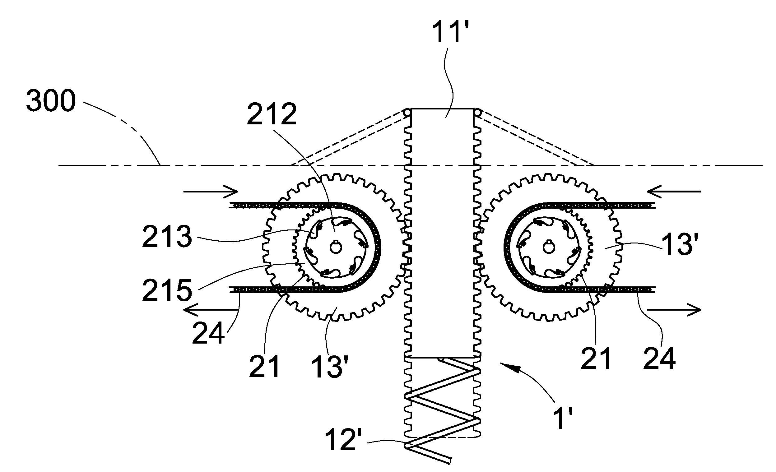
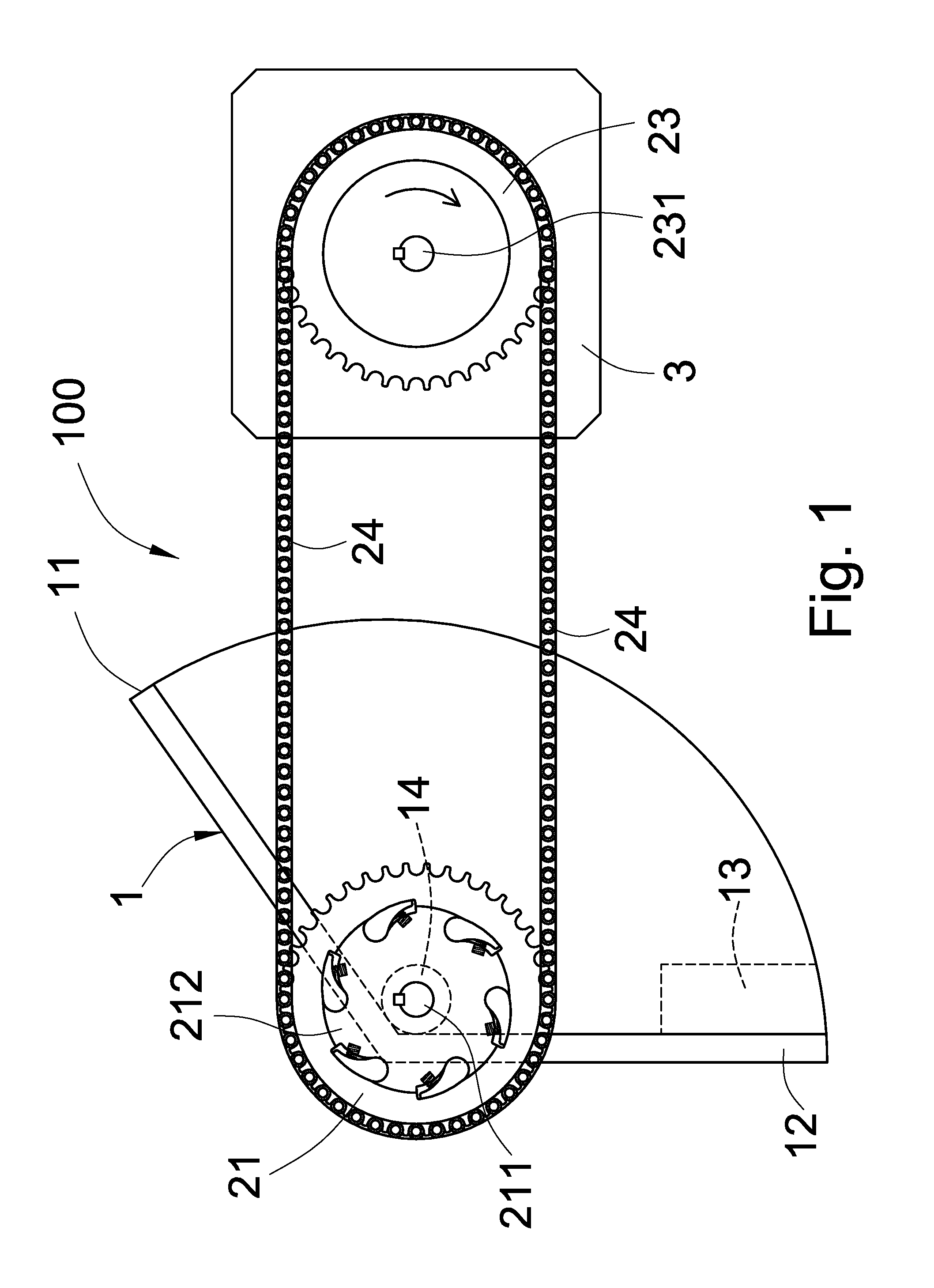
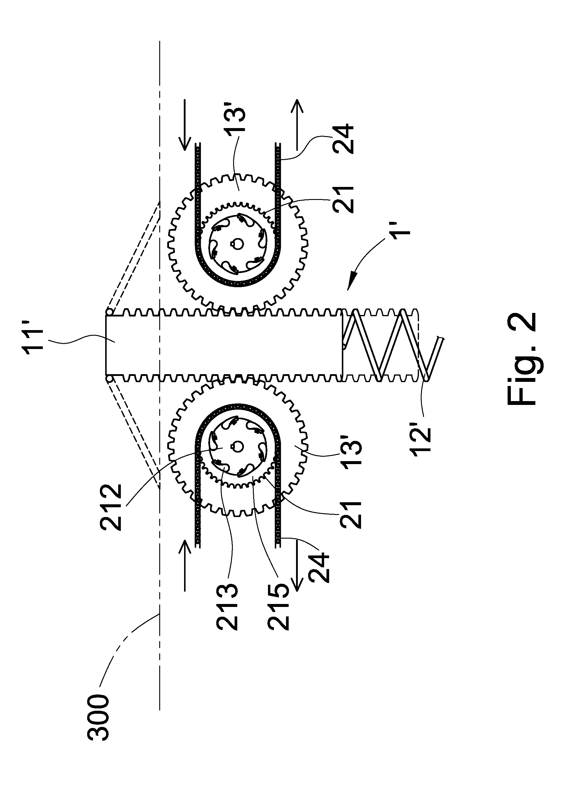
[0022]Referring to FIG. 1, the generating device 100 of the present invention includes a driver 1 which further includes a pressure receiver 11 and a restoring element 12 forming a predetermined angle therebetween. The pressure receiver 11 is located above the restoring element 12 and both are engaged each other with a hinge to the mandrel 211. The aforesaid angle formed between the pressure receiver 11 and the restoring element 12 is designed to have a value according to predetermined angular swinging speed of the driver 1. The restoring force of the restoring element 12 is offered by at least a balancing weight 13 whose weight is also determined according to the angular swinging speed of the driver 1. The hinge is enclosed by a sleeve 14, which is also enclosing the mandrel 211 of a driving wheel 21. The whole structure of the present invention is installed beneath the road flush with the road surface 300 except the pressure receiver 11 being emerged out the road surface 300.

[0023...


PUM


Abstract

In an electricity generating device by applying vehicle weight, a rolling vehicle wheel is weighting down on a pressure receiver to actuate a driving mechanism having a restoring function. It is then able to provide a unidirectional rotating torque to drive a generating device to produce electrical power. The mechanical power transmission is performed by a transmission gear unit composed of a driving wheel and a follower wheel interconnected each other with a transmission means therebetween. When the vehicle weight is applied to the driving mechanism by pressing the vehicle wheel on the pressure receiver, the driving mechanism is forced to downwardly urge a ratchet wheel and a driving wheel to rotate that in turn causes the rotation of the follower wheel through the transmission means thereby driving the generating device to operate to produce electricity. The driving mechanism can recover its initial state with the aid of a balancing weight as soon as it has been liberate from the exerted pressure of the vehicle wheel. The device is to be installed flush with the road surface to work.

Description

BACKGROUND OF THE INVENTION[0001]1. Field of the invention[0002]The present invention relates to an electricity generating device by applying vehicle weight, and in particular, to a generating device when a rolling vehicle wheel is weighting down on a pressure receiver, a driving mechanism installed flush with the road surface is actuated to drive the electricity generating device to output the electric power.[0003]2. Description of the Prior Art[0004]Rising of the environmental consciousness to save energy and minimize carbon producing has become common all over the world. The technique of energy saving and development of various new electric generation means is a paramount importance to harbingers who are working in the front of scientific fields.[0005]From the latter parts of the 20th century up to now, the bulk power station plays the most essential roll on the power generation to provide all the power demand by the society. Meanwhile, the public power service including the traf...

Claims


Application Information

Patent Timeline
Patent Type & Authority Applications(United States)
IPC IPC(8): F03G3/00
CPCH02K7/1853F03G7/08
Inventor CHEN, MING-CHENG
Owner CHEN MING CHENG
Learn More