Yarn layer forming apparatus, yarn layer forming method, and method of manufacturing fiber-reinforced member

a technology of yarn and fiber reinforcement, applied in the direction of braid, textiles and paper, coating, etc., can solve the problems of wavyness due to woven fabric (or meandering), weight reduction, environmental impact reduction,

Inactive Publication Date: 2010-03-04
TOYOTA JIDOSHA KK +1
View PDF2 Cites 50 Cited by
  • Summary
  • Abstract
  • Description
  • Claims
  • Application Information

AI Technical Summary

Benefits of technology

[0009]The invention provides a yarn layer forming apparatus and yarn layer forming method that are able to form a layer of fiber yarn on mandrels having various linear shapes and various cross-sectional shapes while preventing arrangement of fiber yarn, formed on the peripheral surfaces of the mandrels, from losing without forming waviness in fiber yarn that constitutes a fiber-reinforced member, and a method of manufacturing the fiber-reinforced member.
[0013]However, when only yarn arrangement layers are formed on the peripheral surface of a mandrel, or the like, particularly having a curved shape, the yarn arrangement layers are misaligned, and it is difficult to maintain the positions of the yarn arrangement layers when they were formed. Therefore, for example, the peripheral surface of the two yarn arrangement layers is surrounded by a woven layer formed by the braider to make it possible to prevent a misalignment of the positions of the yarn arrangement layers.
[0016]With the yarn layer forming apparatus according to the first aspect of the invention, it is possible to form multiple yarn arrangement layers having no waviness and a woven layer that prevents a misalignment of the yarn arrangement layers on the peripheral surface of a mandrel on top of one another by an extremely simple apparatus formed of just a combination of a plurality of supply means and a braider. In addition, the above method does not wind yarn on peripheral surface of the mandrel while rotating the mandrel unlike a filament winding method. Therefore, even in the case of a curved mandrel or, further, in the case where the cross-sectional shape of the mandrel varies, it is possible to easily form a fiber yarn layer on the peripheral surface of the mandrel with high accuracy.
[0019]With the yarn layer forming method according to the second aspect of the invention, even when the mandrel has a curved shape or has a complex cross-sectional shape or the shape of the mandrel varies, it is possible to easily form yarn arrangement layers on the peripheral surface of the mandrel without waviness by the supply means that rotate or do not rotate. In addition, the woven layer is formed by the braider on the peripheral surface of the yarn arrangement layers to make it possible to press the yarn arrangement layers from the outside. This can effectively prevent a misalignment of the yarn arrangement layers.
[0022]As can be understood from the above description, with the yarn layer forming apparatus according to the aspect of the invention and the yarn layer forming method that uses the yarn layer forming apparatus, it is possible to form yarn arrangement layers, having no waviness, and a woven layer, that maintains the arrangement by pressing the yarn arrangement layers from the outside, on the peripheral surface of a mandrel irrespective of the linear shape and / or cross-sectional shape (complexity, variation, or the like) of the mandrel. The intermediate element formed by the yarn layer forming method is subjected to injection molding in a mold die to thereby make it possible to obtain a high-quality fiber-reinforced member (fiber-reinforced plastic member: FRP member) that has high strength characteristics (bending strength, torsional strength, shearing strength, and the like).

Problems solved by technology

In recent vehicle development, safety, weight reduction, and environmental impact reduction are significant challenges than ever before.
However, when the braider is used to form a woven fabric on the peripheral surface of the mandrel, waviness due to the woven fabric (or meandering due to intersections of yarns) occurs.

Method used


Image

  • Yarn layer forming apparatus, yarn layer forming method, and method of manufacturing fiber-reinforced member
  • Yarn layer forming apparatus, yarn layer forming method, and method of manufacturing fiber-reinforced member
  • Yarn layer forming apparatus, yarn layer forming method, and method of manufacturing fiber-reinforced member

Examples


Embodiment Construction

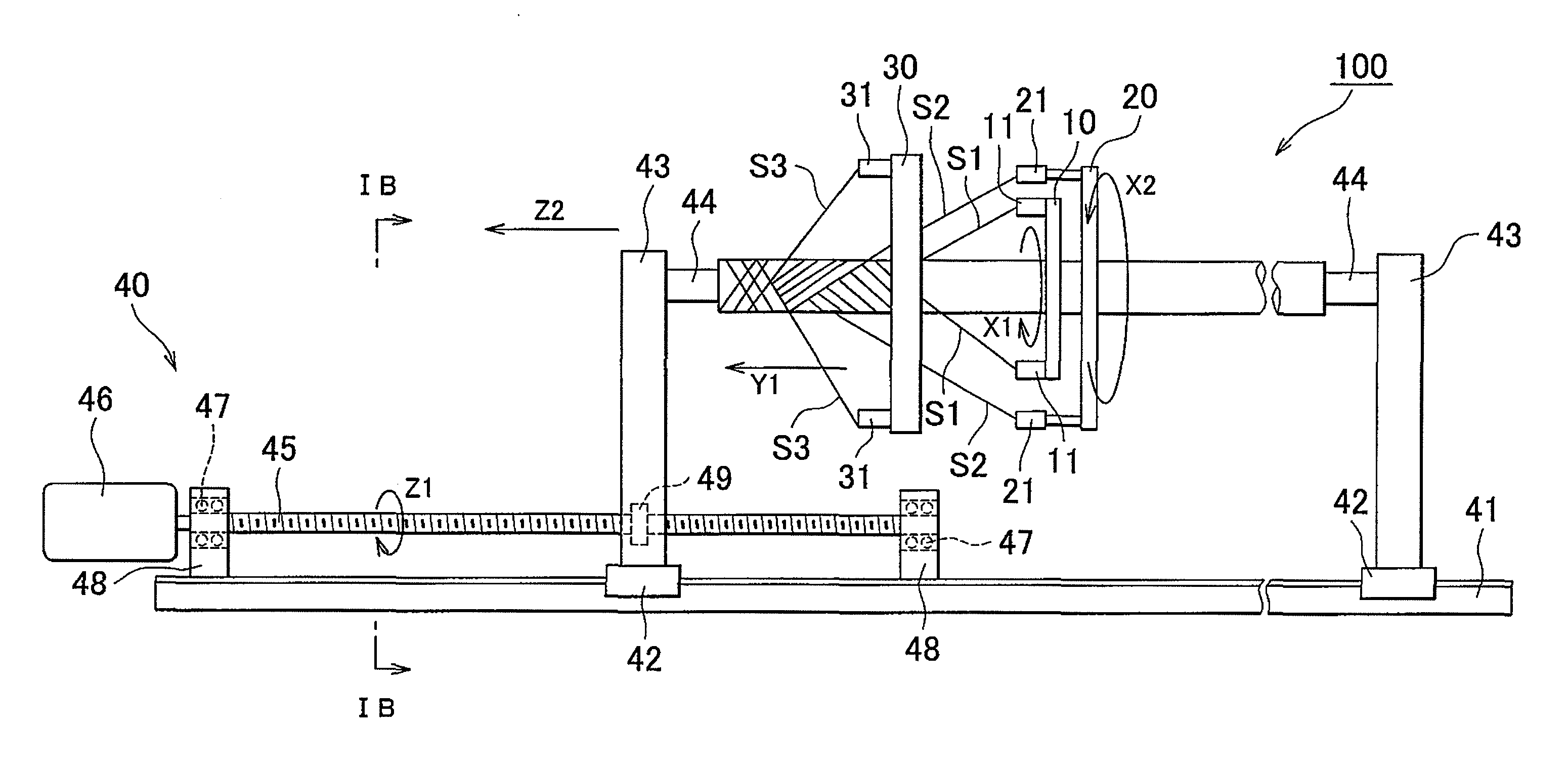
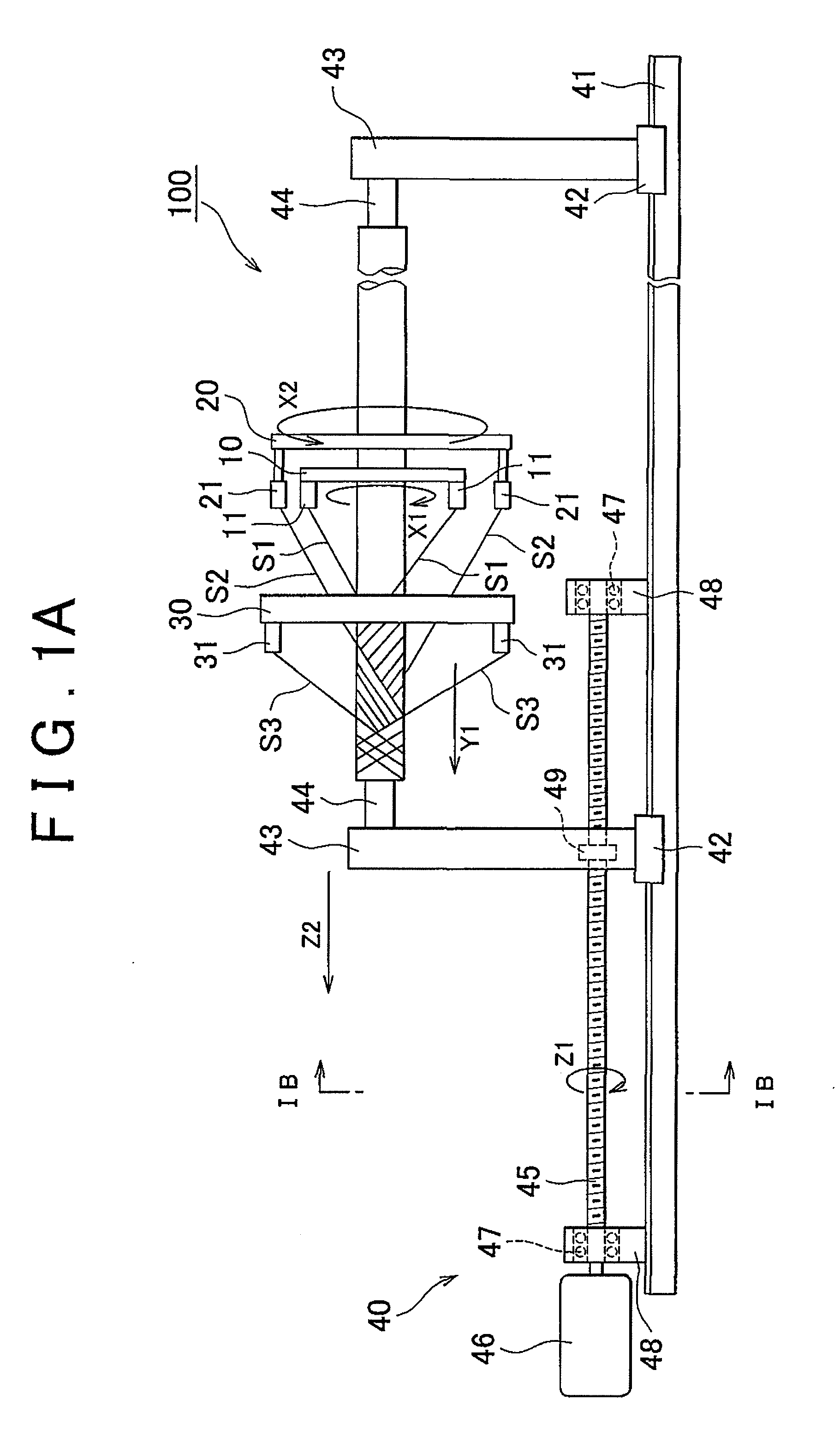
[0028]Hereinafter, an embodiment of the invention will be described with reference to the accompanying drawings. FIG. 1A is a side view that schematically illustrates a yarn layer forming apparatus according to the embodiment of the invention, and FIG. 1B is a cross-section at view that is taken along the line IB-IB in FIG. 1A. The yarn layer forming apparatus 100 mainly includes an annular braider 30, an annular first supply member 10, an annular second supply member 20, and an actuator 40. The first supply member 10 is located at a distance from the braider 30. The second supply member 20 is located at a distance from the first supply member 10. The actuator 40 moves a mandrel M inside these annular components.

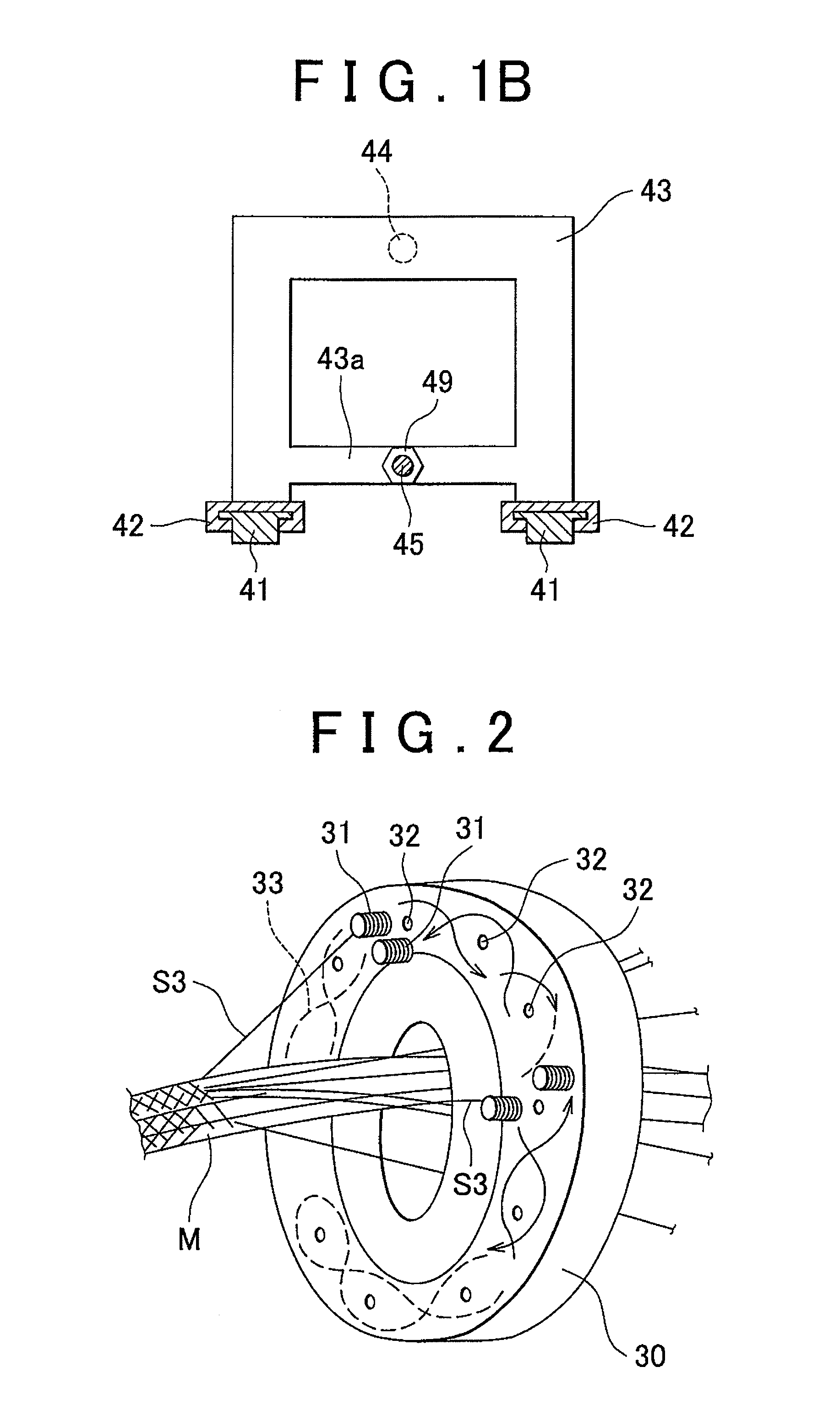
[0029]This will be described with reference to FIG. 2 that illustrates the braider 30 further in detail. Many gears are installed inside the annular braider 30 in the circumferential direction. A bobbin movement groove 33 is formed in a figure-of-eight meander shape so as to...


PUM

PropertyMeasurementUnit
distanceaaaaaaaaaa
layer structureaaaaaaaaaa
water-solubleaaaaaaaaaa

Abstract

A yarn layer forming apparatus includes: an annular braider that supplies braider yarn; an annular first supply device that supplies first yarn; an annular second supply device that supplies second yarn; and an actuating device that moves a mandrel. At least one of the first supply device and the second supply device is rotatable. A layer structure of yarn layers is formed on a peripheral surface of the mandrel. The layer structure of yarn layers includes at least yarn arrangement layers formed respectively by the first and second supply devices and a woven layer formed by the braider.

Description

INCORPORATION BY REFERENCE[0001]The disclosure of Japanese Patent Application No. 2008-226197 filed on Sep. 3, 2008 including the specification, drawings and abstract is incorporated herein by reference in its entirety.BACKGROUND OF THE INVENTION[0002]1. Field of the Invention[0003]The invention relates to a yarn layer forming apparatus and yarn layer forming method that form multiple yarn layers by stacking the multiple yarn layers, for example, on a peripheral surface of a long mandrel, and further to a method of manufacturing a fiber-reinforced member using an intermediate element formed by the yarn layer forming method.[0004]2. Description of the Related Art[0005]In recent vehicle development, safety, weight reduction, and environmental impact reduction are significant challenges than ever before. For hybrid vehicles, electric vehicles, and the like, that currently become the focus of attention, a fiber-reinforced member is applied to various components of the vehicles. The fibe...

Claims


Application Information

Patent Timeline
Patent Type & Authority Applications(United States)
IPC IPC(8): D04C1/06D04C3/00D04C3/24B29C45/00
CPCB29C45/14631B29C70/20B29C70/22B29C70/32D10B2505/02D04C3/36D04C3/48D04C3/08D04C1/06
Inventor INAZAWA, KOICHIHORI, FUJIO
Owner TOYOTA JIDOSHA KK
Why Eureka
Try Eureka