
Apparatus for lighting leds

a technology of led lights and led strips, applied in the direction of electric variable regulation, process and machine control, instruments, etc., can solve the problems of increasing the thickness of the board, increasing the cost of film capacitors, and generating noise of capacitors cb>27/b>, and achieve the effect of low cos

Active Publication Date: 2010-03-04
SANKEN ELECTRIC CO LTD
View PDF6 Cites 31 Cited by
  • Summary
  • Abstract
  • Description
  • Claims
  • Application Information

AI Technical Summary

Benefits of technology

The present invention provides an apparatus for lighting LEDs that produces no noise during a PWM dimming operation, is low-profile, and is manufacturable at low cost. The apparatus includes an LED group load, a converter, a current controller, a voltage controller, a time division circuit, and a selector. The selector selects the current controller or the voltage controller to control the output voltage provided by the converter, depending on the current passing through the LED group load. The current controller generates a current feedback signal and the voltage controller generates a voltage feedback signal, which the selector uses to PWM-control the output voltage provided by the converter. This results in a low-profile, low-cost solution for lighting LEDs that produces no noise during PWM dimming operation.

Problems solved by technology

The electrolytic capacitors, however, increase board thickness and the film capacitors heighten cost, and therefore, the chip ceramic capacitors have the preference.
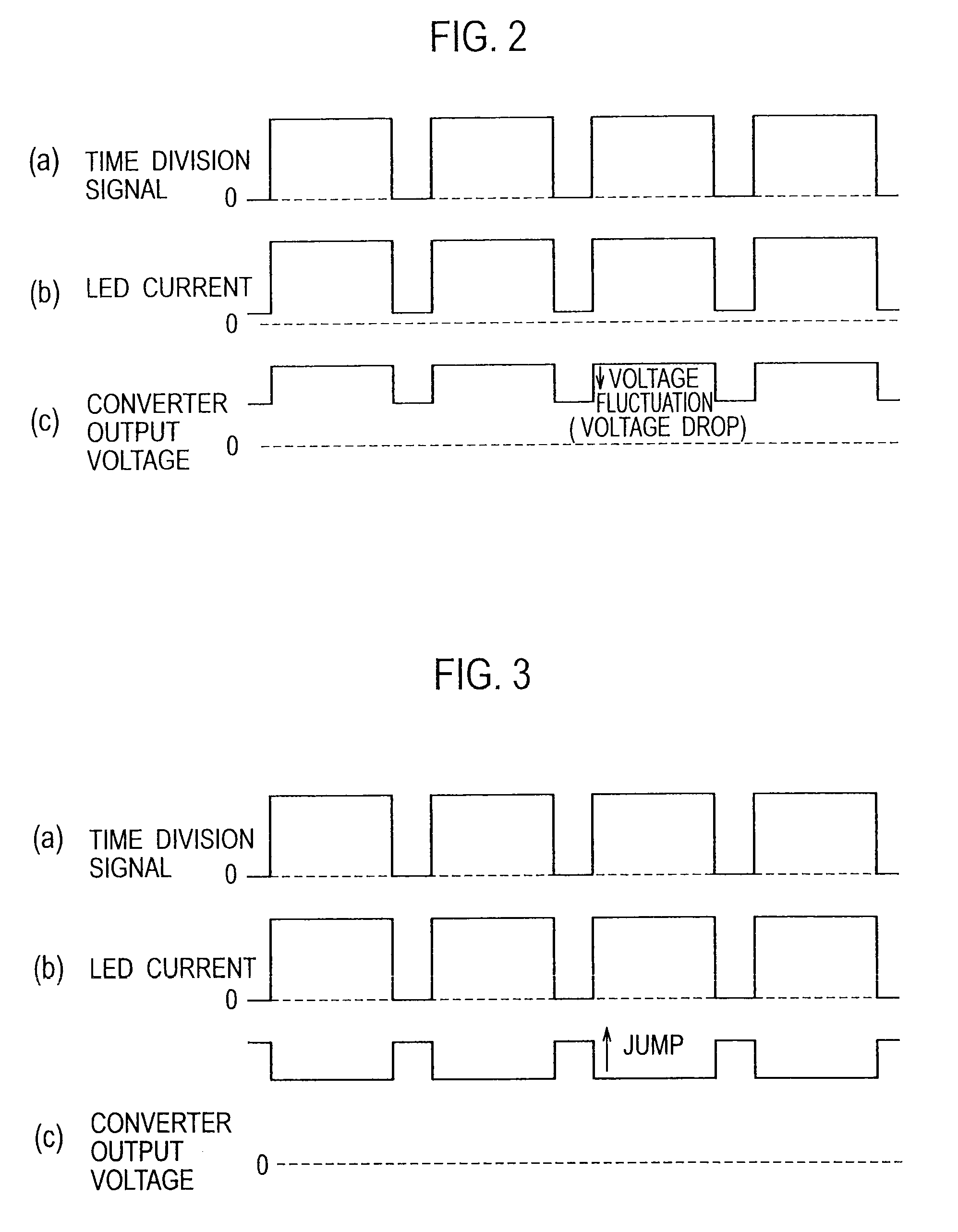
This, however, causes the capacitor C27 to generate noise.

Method used


Image

  • Apparatus for lighting leds
  • Apparatus for lighting leds
  • Apparatus for lighting leds

Examples


Embodiment Construction

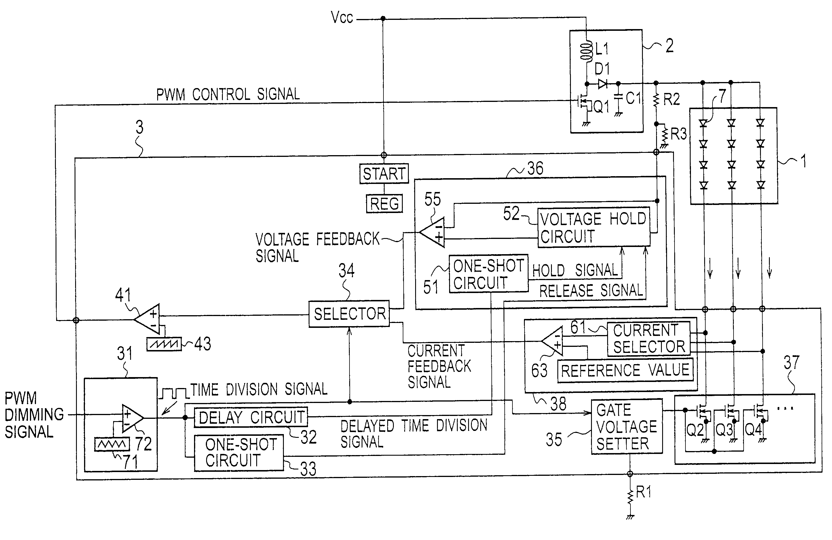
[0021]An apparatus for lighting LEDs according to an embodiment of the present invention will be explained.

[0022]FIG. 4 is a block diagram illustrating the apparatus according to the embodiment. The apparatus includes an LED group load 1, a converter 2, a controller 3, and a resistor R1 for setting gate voltage.

[0023]The LED group load 1 includes a plurality of LEDs 7 to form a backlight 1. The LEDs 7 are separated into LED groups each having a plurality of series-connected LEDs. The LED groups are connected in parallel with one another. In FIG. 4, there are three LED groups those are connected in parallel with one another. The number of LED groups to be connected in parallel is optional. The LED group load 1 is connected between an output end of the converter 2 and a sink driver 37 arranged in the controller 3.

[0024]The converter 2 is, for example, a boost chopper and includes a step-up reactor L1, a switching element Q1 made of a MOSFET, a diode D1, and a capacitor C1. In response...


PUM


Abstract

An apparatus for lighting LEDs includes an LED group load having the LEDs, a converter to generate a voltage applied to the LED group load, a current controller to control a current of the LED group load, a voltage controller to control an output voltage provided by the converter, a time division circuit to intermittently pass a current through the LED group load, and a selector. The selector, during a period in which the time division circuit passes a current through the LED group load, selects the current controller to control a current of the LED group load and thereby control an output voltage provided by the converter, and during a period in which the time division circuit passes no current through the LED group load, selects the voltage controller to control an output voltage provided by the converter.

Description

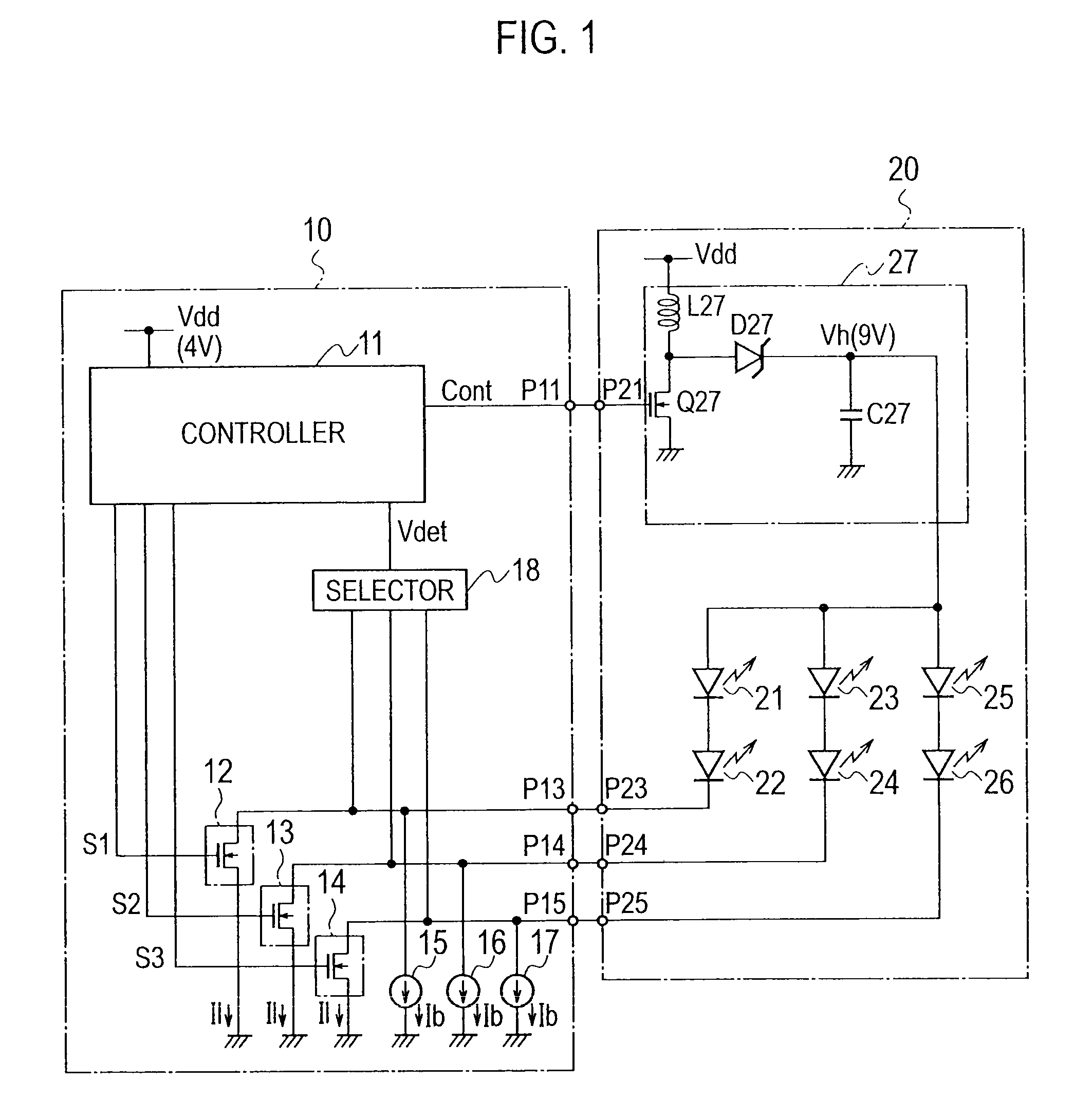
BACKGROUND OF THE INVENTION[0001]1. Field of the Invention[0002]The present invention relates to an apparatus for lighting LEDs (Light Emitting Diodes) used as, for example, a backlight for a liquid crystal display.[0003]2. Description of the Related Art[0004]An example of an apparatus for lighting LEDs is disclosed in, for example, Japanese Unexamined Patent Application Publication No. 2003-332624. This related art lights groups of series-connected LEDs with a voltage that is set to be always lower than a power source voltage irrespective of the number of the groups of series-connected LEDs, thereby enabling the use of low-withstand-voltage ICs and reducing a power loss.[0005]FIG. 1 illustrates the apparatus according to the above-mentioned related art. The apparatus includes drivers 12 to 14 that turn on / off in response to time division signals S1 to S3. First ends of the drivers 12 to 14 are connected to terminals P23 to P25 that are connected to LEDs 21 to 26. The drivers 12 to ...

Claims


Application Information

Patent Timeline
Patent Type & Authority Applications(United States)
IPC IPC(8): H05B37/02
CPCH05B33/0815Y02B20/347H05B33/0827H05B33/0818H05B45/38H05B45/46Y02B20/30
Inventor KIMURA, KENGO
Owner SANKEN ELECTRIC CO LTD
Learn More