Lamp driver circuit and method for driving a discharge lamp

a technology of lamp driver circuit and discharge lamp, which is applied in the direction of instruments, light sources, electrical devices, etc., can solve the problems of not being suitable for driving such a discharge lamp, open-loop lamp driver circuit may not be suitable for regulating output power, and the impedance of the lamp may exhibit steep changes

Inactive Publication Date: 2010-03-04
KONINKLIJKE PHILIPS ELECTRONICS NV
View PDF5 Cites 58 Cited by
  • Summary
  • Abstract
  • Description
  • Claims
  • Application Information

AI Technical Summary

Benefits of technology

[0012]In an embodiment, the low-speed feedback circuit is configured to receive a set frequency, i.e. a predetermined or selected frequency. Further, the low-speed feedback circuit is configured to determine the operating frequency and to control the DC supply voltage in response to a frequency difference between the operating frequency and the set frequency. In response, the high-speed feedback circuit may adjust the operating frequency towards the set frequency. Thus, a course and fine control method is obtained, thereby preventing interference between the high-speed and the low-speed feedback circuit. As the bandwidth of the high-speed feedback circuit is substantially higher than the bandwidth of the low-speed feedback circuit, the high-speed feedback circuit will track the DC supply voltage changes of the low-speed feedback circuit. Hence, the high-speed feedback circuit is dominant over the low-speed feedback circuit.

Problems solved by technology

Further, during run-up the impedance of the lamp may exhibit steep changes.
Thus, an open-loop lamp driver circuit may not be suitable for driving such a discharge lamp, since the open-loop lamp driver circuit cannot ensure stable operation of the lamp.
Due to the above-mentioned steep relations, an open-loop lamp driver circuit may not be suitable for regulating the output power.
However, due to EMI regulations, the frequency range for control may be limited, not allowing both controlling stability and regulating power, in particular not during run-up and for dimming.
However, due to the presence of a relative large capacitance for energy buffering at the DC-voltage bus, such a control system is relatively slow, whereas a relatively fast control is required for stability control.

Method used


Image

  • Lamp driver circuit and method for driving a discharge lamp
  • Lamp driver circuit and method for driving a discharge lamp
  • Lamp driver circuit and method for driving a discharge lamp

Examples


Embodiment Construction

[0023]Hereinafter, same reference numerals refer to similar elements.

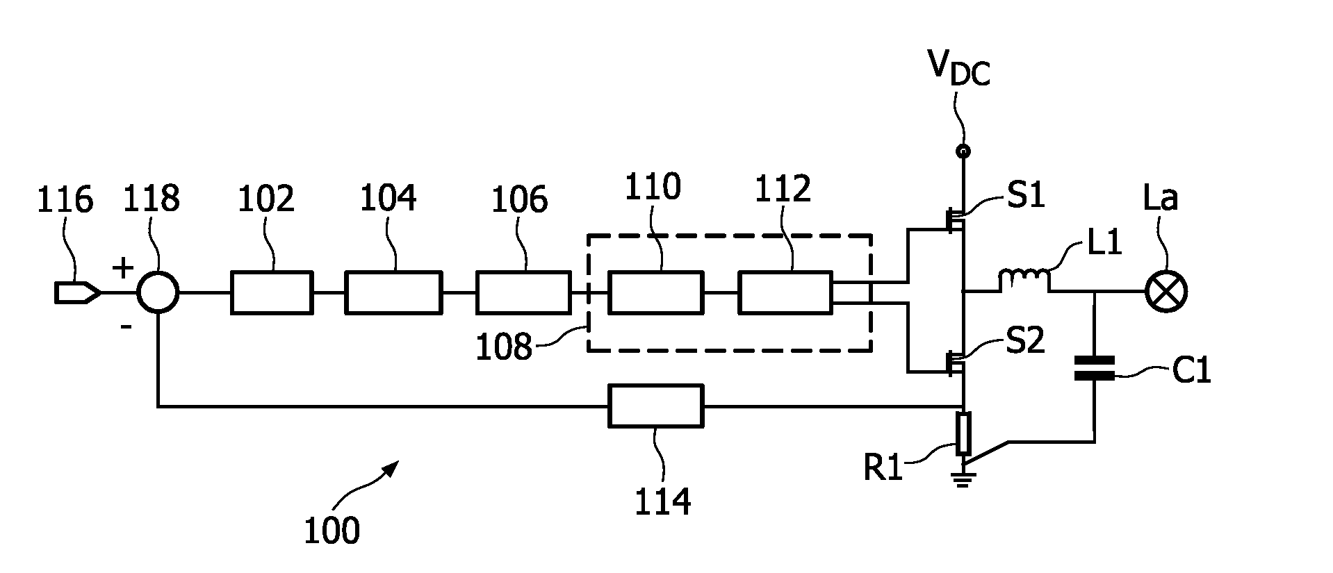
[0024]FIG. 1 shows a diagram illustrating a relation between a lamp voltage V (at the horizontal axis) and a lamp power P (at the vertical axis) of a discharge lamp, in particular an inductively coupled discharge lamp, such as a molecular radiation lamp. The lamp voltage V is the voltage over the lamp terminals during lamp operation. At a lamp power level A, the lamp voltage V may vary without directly influencing the lamp power P, since the shown curve is substantially flat. So, the discharge lamp may be stably operated at power level A.

[0025]If the discharge lamp is to be operated at a different power level, e.g. power level B, due to the steep relation between the lamp voltage V and the lamp power P, a feedback circuit is required in the lamp driver circuit in order to maintain stable operation.

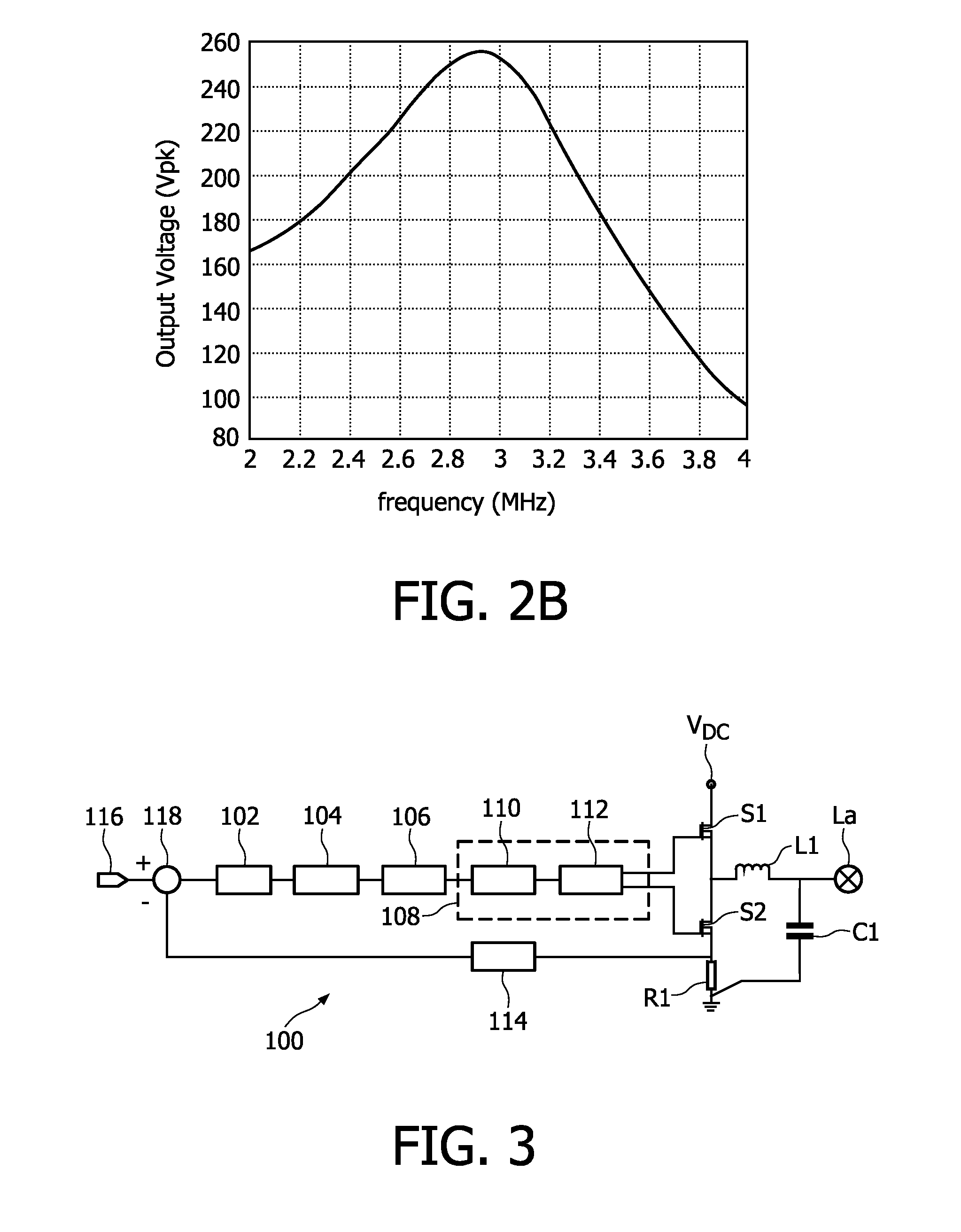
[0026]The feedback circuit may control a frequency of an AC current supplied to the lamp, as is known in the art. FIG. ...


PUM


Abstract

A lamp driver circuit (400) comprises a feedback circuit for controlling stable operation of a discharge lamp (La), e.g. an inductively coupled discharge lamp such as a molecular radiation lamp, and for controlling a light output level of the discharge lamp (La). In particular, if the discharge lamp (La) is operated at a dimmed light output level, the light output is sensitive to changes in the lamp voltage (VLa), possibly resulting in flickering. In order to control stable lamp operation and prevent flickering, a high-sp feedback circuit is provided for controlling an operating frequency. In order to provide a relatively large dimming range for controlling the light output level, a low-speed feedback circuit is provided for controlling a DC supply voltage level (VDC).

Description

FIELD OF THE INVENTION[0001]The present invention relates to a lamp driver circuit and a method of driving a discharge lamp. In particular, the present invention is suitable to be employed for driving a discharge lamp exhibiting steep impedance changes as a function of lamp voltage.BACKGROUND OF THE INVENTION[0002]It is known in the art to operate a discharge lamp using an open-loop lamp driver circuit. The lamp driver circuit comprises an inverter circuit for generating a suitable AC current for driving the lamp. Such an open-loop driver circuit may be calibrated during manufacturing with respect to the output power.[0003]A known discharge lamp, e.g. an inductively coupled discharge lamp such as a molecular radiation lamp, may exhibit a steep relation between an output power and a voltage over the lamp terminals. The lamp voltage depends, inter alia, on a frequency of the supplied AC current, the output power thereby being depended on the frequency of the supplied AC current. Furth...

Claims


Application Information

Patent Timeline
Patent Type & Authority Applications(United States)
IPC IPC(8): H05B41/26
CPCH05B41/3925
Inventor VAN DER VEEN, GEERT WILLEMDELNOIJ, ROGER PETER ANNA
Owner KONINKLIJKE PHILIPS ELECTRONICS NV
Why Eureka
Try Eureka