
Servo motor control apparatus and control method

Active Publication Date: 2010-03-04
PANASONIC CORP
View PDF1 Cites 20 Cited by
  • Summary
  • Abstract
  • Description
  • Claims
  • Application Information

AI Technical Summary

Benefits of technology

[0017]With such configurations, changing control parameters, for example, exercises control so as to narrow the frequency band width of the feedback loop even in the case of occurrence of oscillation in the feedback loop, thereby it is possible to stop the oscillation promptly, keep damage inflicted to the load of the servo motor at the minimum and also perform adjustment of the control parameters smoothly in a short period of time.

Problems solved by technology

Further, when the value of position gain Kp is not appropriately given with respect to the value of velocity band fv, a damping factor of feedback loop 104 is affected, resulting in that an appropriate response cannot be obtained with respect to the command from outside due to vibrational response or, on the contrary, deterioration in tracking of the rotational position.
However, even when the auto tuning is executed, the control parameters are not necessarily adjusted to optimal values with respect to any state of the load, and hence in the actual situation, the manual adjustment function has also been essential for a typical servo motor control apparatus.
Further, no matter whether manual adjustment or auto tuning is performed, in the case of raising or lowering the respective control parameters for adjustment to the optimal values, oscillation occurs in the feedback loop, leading to strong vibration of the servo motor, which might damage the load of the servo motor.
There has thus been a problem with such a conventional servo motor control apparatus in that it takes a long time to stop the oscillation, to cause excessive damage on the load of the servo motor, or time and efforts to be expensed for adjustment of the control parameters.

Method used


Image

  • Servo motor control apparatus and control method
  • Servo motor control apparatus and control method
  • Servo motor control apparatus and control method

Examples


embodiment 1

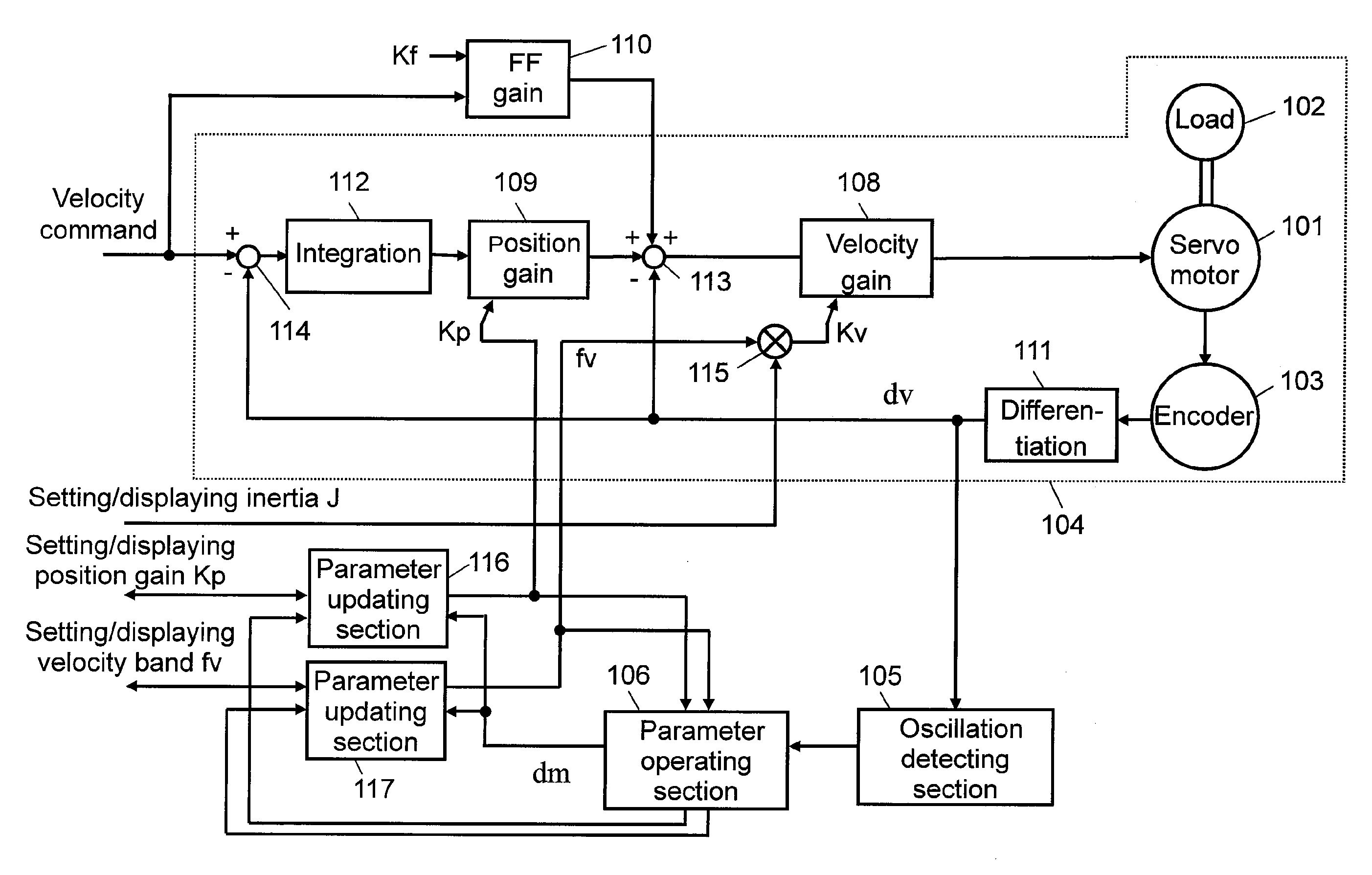
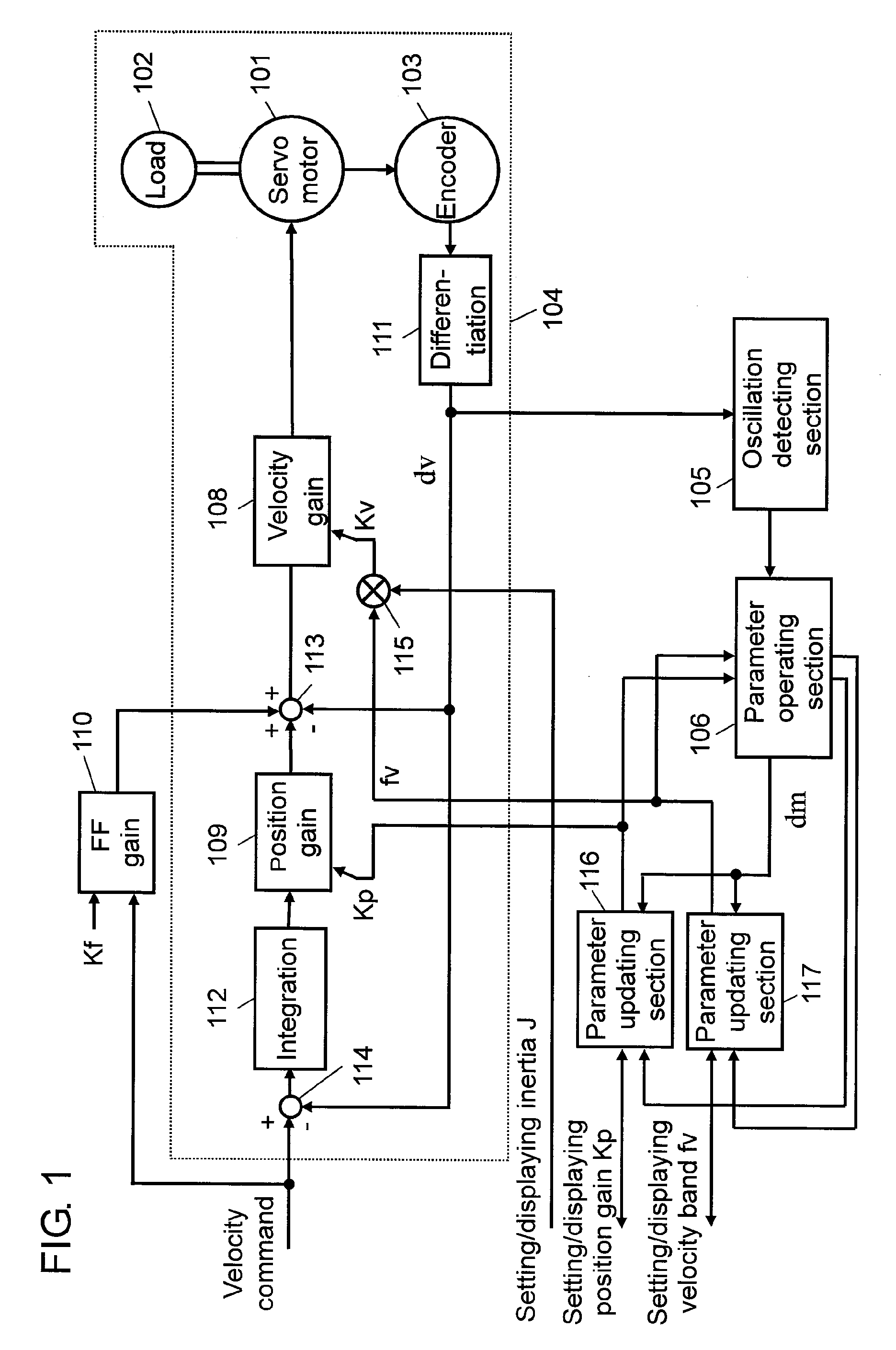
[0083]FIG. 1 is a block diagram of a servo motor control apparatus in Embodiment 1 of the present invention. In the present embodiment, a description is given, taking an example of a servo motor control apparatus (hereinafter simply referred to as “control apparatus” as appropriate) in which a motor rotational position is detected to configure a feedback loop so as to track a velocity command inputted from the outside and is also capable of manually setting appropriate set value for a plurality of control parameters included in the feedback loop, such as a velocity gain and a position gain.

[0084]In FIG. 1, servo motor 101 (hereinafter referred to as “motor” as appropriate) is connected with encoder 103 for detecting a rotational position. Encoder 103 outputs a position detection signal indicating a value corresponding to the detected rotational position of motor 101. The position detection signal is subjected to differential operation processing in differential operation section 111...

embodiment 2

[0130]FIG. 7 is a block diagram of a servo motor control apparatus in Embodiment 2 of the present invention. In comparison with Embodiment 1, parameter updating section 118 which captures a set value of inertia J as a control parameter from the outside, and updates a value in accordance with this set value is further provided in Embodiment 2. Further, parameter updating sections 116, 117, and 118 constitute the updating section. It is to be noted that in FIG. 7, the same constituents as those in FIG. 1 are provided with the same reference numerals as those in FIG. 1, and detailed descriptions thereof are not given.

[0131]In FIG. 7, parameter updating section 118 is provided with a set value of inertia J from the external host equipment or the like. Parameter updating section 118 outputs the optimal set value of inertia J as an output value in accordance with an operational instruction of parameter operating section 106. The output value of inertia J outputted from parameter updating ...

embodiment 3

[0138]FIG. 8 is a block diagram of a servo motor control apparatus in Embodiment 3 of the present invention. In comparison with Embodiment 1, parameter setting section 130 and stiffness value updating section 131 are provided in place of parameter updating sections 116 and 117 in Embodiment 3. Further, parameter setting section 130 and stiffness value updating section 131 constitute the updating section. It is to be noted that in FIG. 8, the same constituents as those in FIG. 1 are provided with the same reference numerals as those in FIG. 1, and detailed descriptions thereof are not given.

[0139]Further, in the present embodiment, a stiffness set value whose value range has previously been determined is selected and set from the external host equipment or the like, thereby to form a configuration where the control parameters in accordance with stiffness of the load can be set. Namely, for example, eight ranks of stiffness set value from “0” to “7” are previously set, and the value i...


PUM


Abstract

A servo motor control apparatus having a feedback loop includes: an oscillation detecting section, which detects oscillation of the feedback loop, to output an oscillation detection signal; a parameter operating section, which gives an operational instruction to set a control parameter in the feedback loop based upon the oscillation detection signal; and an updating section, which is supplied with a set value for setting a control parameter, and sets the control parameter in the feedback loop while making an update thereon in accordance with the operational instruction given by the parameter operating section, wherein when the oscillation detection signal indicates no detection of oscillation, the parameter operating section gives the updating section an operational instruction to set a control parameter in accordance with the supplied set value, and when the oscillation detection signal indicates detection of oscillation, parameter operating section gives the updating section an operational instruction to set such a control parameter as to narrow a frequency band width of the feedback loop.

Description

TECHNICAL FIELD[0001]The present invention relates to a control apparatus and a control method for mainly controlling an industrial FA servo motor.BACKGROUND ART[0002]In a control apparatus for driving a servo motor, a feedback loop is generally configured for detecting a rotational velocity or a rotational position of the motor so as to track a velocity command or a position command inputted from outside. In order to ensure operational stability of the feedback loop to sufficiently exert performance for tracking the velocity command or the position command, it is necessary to set appropriate values for a plurality of control parameters included in the feedback loop, namely a velocity gain and a position gain, in accordance with a moment of inertia and a state of the load of the servo motor.[0003]A conventional servo motor control apparatus is mounted with parameter setting means for setting an appropriate value for the foregoing control parameter in accordance with the moment of in...

Claims


Application Information

Patent Timeline
IPC IPC(8): G05B13/02G05B5/01H02P29/00
CPCH02P23/0068H02P23/005H02P23/22H02P23/18
Inventor KISHIMOTO, KENICHITAZAWA, TOORU
Owner PANASONIC CORP
Learn More