Capacitive sensor

a capacitive sensor and sensor technology, applied in the field of capacitive sensors, can solve the problem of the input device being more sensitive to the influence of noise from the circumferen

Inactive Publication Date: 2010-03-04
ROHM CO LTD
View PDF6 Cites 100 Cited by
  • Summary
  • Abstract
  • Description
  • Claims
  • Application Information

AI Technical Summary

Benefits of technology

[0009]The present invention has been made in view of theses issues and an exemplary purpose of an embodiment is to provide a capacitive sensor in which the influence of a noise is suppressed.

Problems solved by technology

The problem can be solved by increasing the sensitivity of the capacitance-voltage conversion circuit; however, this causes the input device to be more sensitive to the influence of noises from the circumference.

Method used


Image

  • Capacitive sensor
  • Capacitive sensor
  • Capacitive sensor

Examples


Embodiment Construction

[0034]The invention will now be described based on preferred embodiments which do not intend to limit the scope of the present invention but exemplify the invention. All of the features and the combinations thereof described in the embodiment are not necessarily essential to the invention.

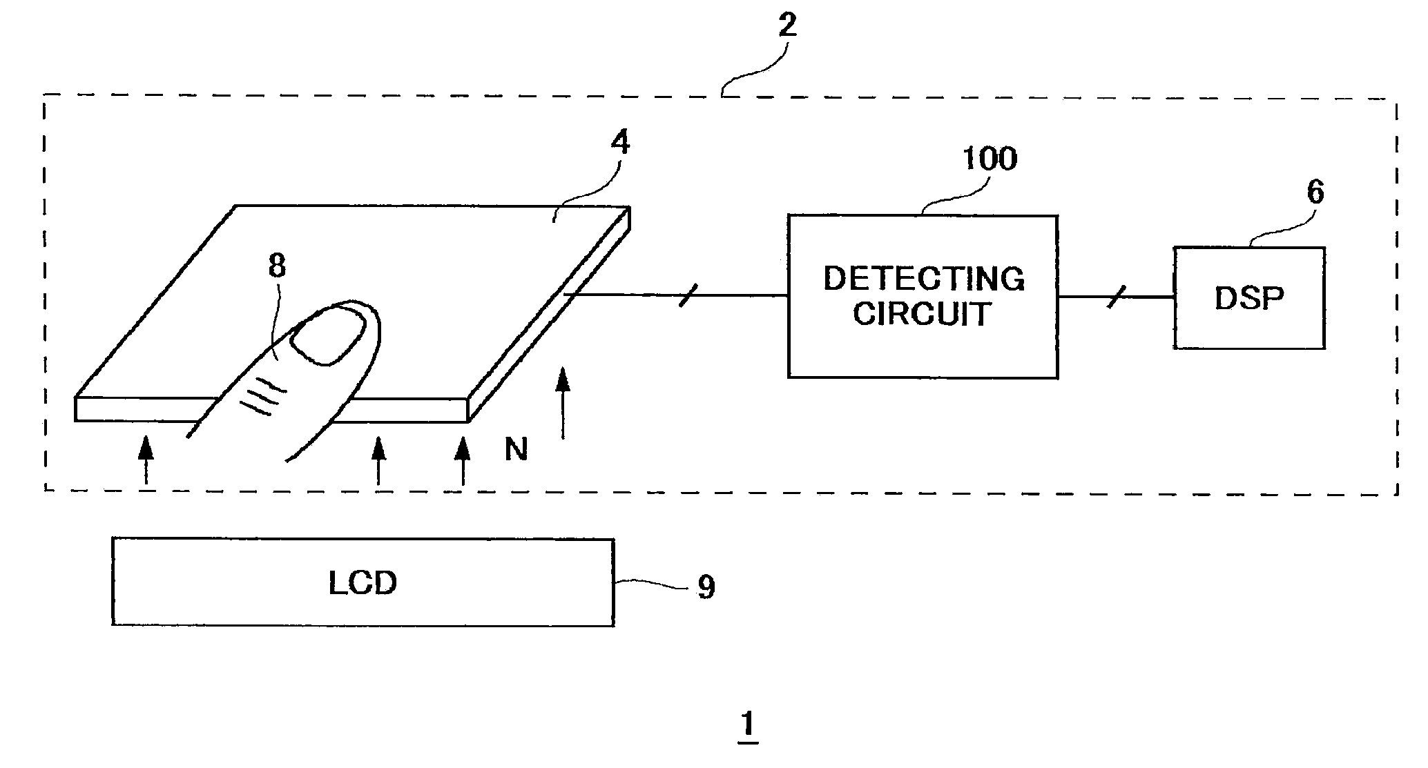
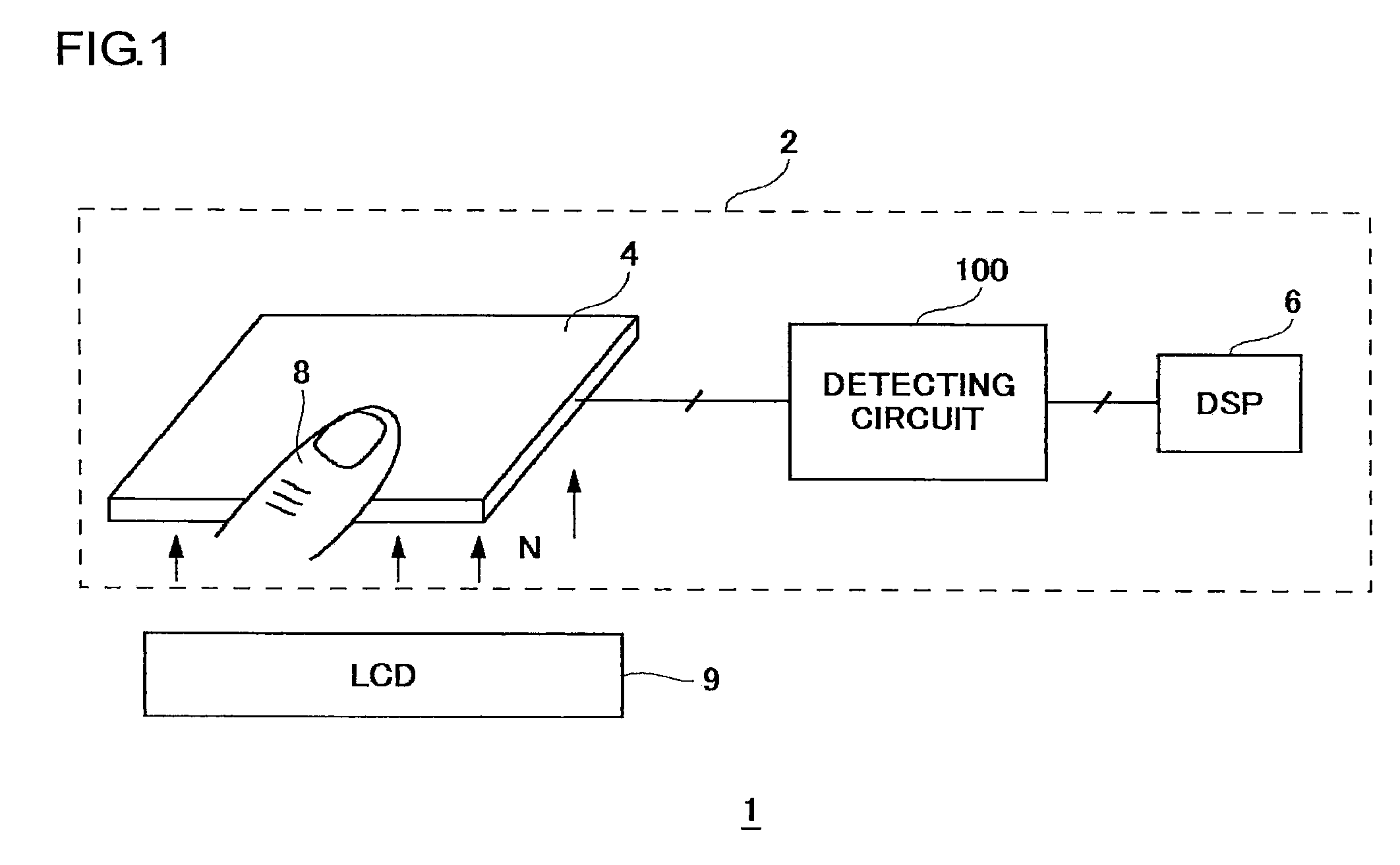
[0035]FIG. 1 is a block diagram illustrating an electronic apparatus 1 comprising the input device 2 according to the embodiment. The input device 2 is arranged, for example, on the surface layer of a Liquid Crystal Display (LCD) 9, functioning as a touch panel.

[0036]The input device 2 comprises: a sensor unit 4; a detecting circuit 100; and a Digital Signal Processor (DSP) 6. When a user touches or puts pressure on the surface of the sensor unit 4 with a finger 8, a sensor electrode (not illustrated) arranged inside the sensor unit 4 is deformed or displaced, causing a change in a capacitance formed thereby around the sensor electrode. The sensor unit 4 may be a switch provided with a single senso...


PUM


Abstract

A shield electrode is provided in parallel with a sensor electrode. A detecting circuit detects a capacitance formed thereby around the sensor electrode. A capacitance-voltage conversion circuit converts the capacitance into a voltage by repeating a predetermined sequence. A shield electrode drive unit switches an electric state of the shield electrode in synchronization with the predetermined sequence. The shield electrode drive unit switches an electric state of the shield electrode in accordance with an electric state of the sensor electrode.

Description

BACKGROUND OF THE INVENTION[0001]1. Field of the Invention[0002]The present invention relates to a capacitive sensor that measures a capacitance.[0003]2. Description of the Related Art[0004]In recent electronic apparatuses such as computers, portable telephone terminals and Personal Digital Assistants (PDAs), the apparatuses provided with input devices for operating the apparatuses by putting pressure thereon with users' fingers have become mainstream. As such input devices, joy sticks and touch panels or the like are known.[0005]As such input devices, a capacitance sensor using a change in capacitance formed around an electrode, the change occurring by a user's touch with the electrode, is used.[0006][Patent Document 1] Japanese Patent Application Laid-open No. 2001-325858[0007][Patent Document 2] Japanese Patent Application Laid-open No. 2003-511799[0008]An input device using the aforementioned change in a capacitance is provided with a capacitance-voltage conversion circuit for c...

Claims


Application Information

Patent Timeline
Patent Type & Authority Applications(United States)
IPC IPC(8): G01R27/26
CPCG06F3/044G06F2203/04107H03K17/962H03K2217/960765H03K2217/960705H03K2217/960755H03K2017/9613G06F3/0446
Inventor YANO, SHIGEHIDESAITO, KOICHI
Owner ROHM CO LTD
Why Eureka
Try Eureka