Stage by stage delay current-summing slew rate controller

a current-summing and delay technology, applied in pulse manipulation, pulse technique, instruments, etc., can solve the problems of low slew rate (sr), difficult control, and no linear slew rate, and achieve wide adjusting range and simple structure.

Inactive Publication Date: 2010-03-04
IPGOAL MICROELECTRONICS (SICHUAN) CO LTD
View PDF4 Cites 5 Cited by
  • Summary
  • Abstract
  • Description
  • Claims
  • Application Information

AI Technical Summary

Benefits of technology

[0037]Change f(t) or Δt and N, various kinds of output current can be produced by superposition. The superposition result can produce various driving effect, so that the slew rate of the output voltage can be customized.
[0038]The benefit of the present invention is illustrated as follows. The present invention obtain obtains controllable current source by linearly summing N stages mirror current, so as to adjust the output voltage slew rate. The present invention can be controlled by program, and is simple in structure, has wide adjusting range, can be transplanted and will not be disturbed.

Problems solved by technology

If R!=0, the slew rate (SR) will become small with the increasing of the output voltage, which is not good for the signal establishment.
In prior art No. 1, basically the capacitor-voltage curve is determined by device fabrication, and appears to be none-linear, which means the slew rate is also none-linear and hard to control.
However, such control mechanism is rather complex and prone to be disturbed.
Meanwhile, the precision such controlling is highly process dependent.
However, in general the bandwidth of a feedback loop can not satisfy the demand of a high speed transmission circuit.

Method used


Image

  • Stage by stage delay current-summing slew rate controller
  • Stage by stage delay current-summing slew rate controller
  • Stage by stage delay current-summing slew rate controller

Examples


example i

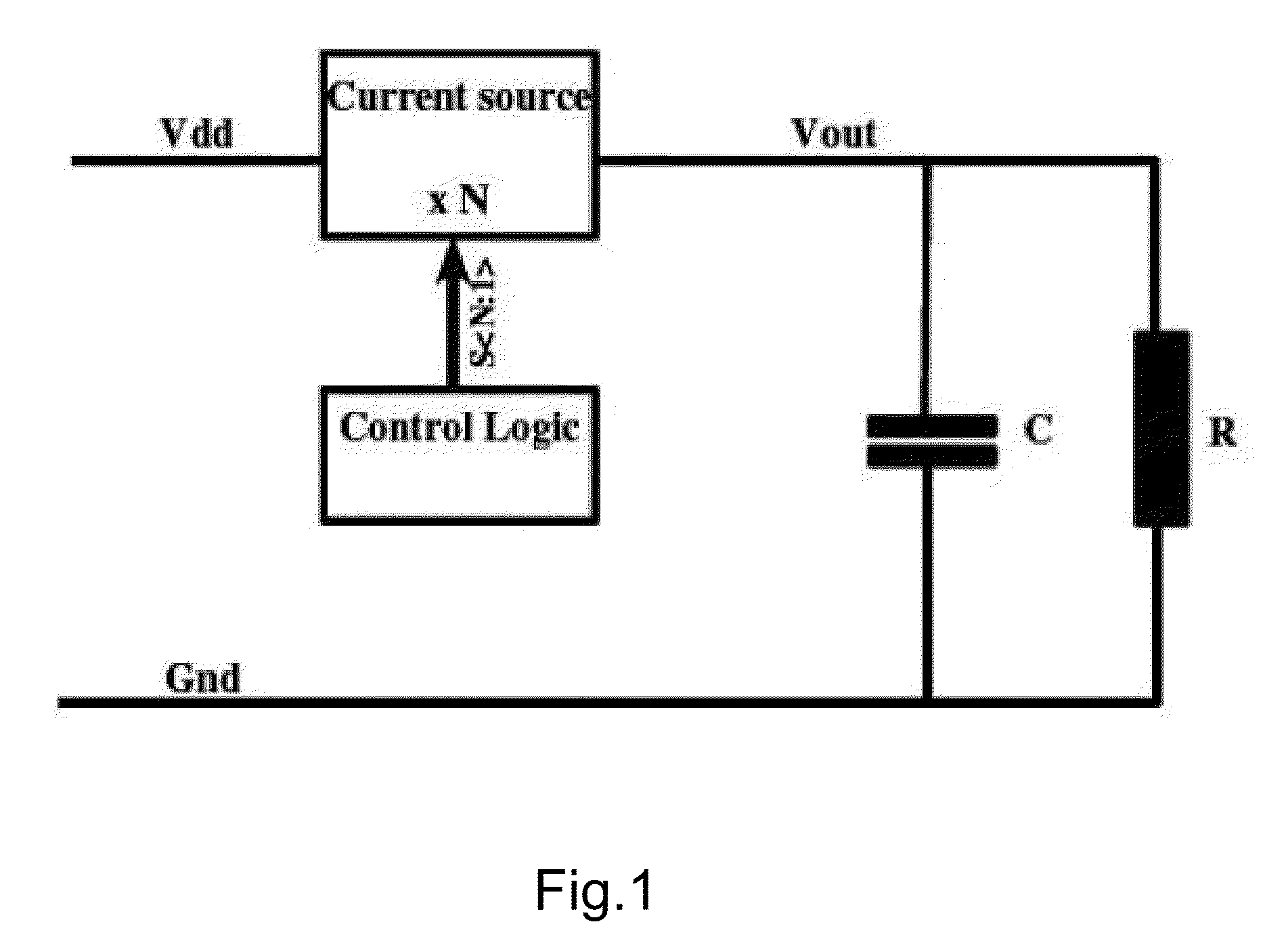
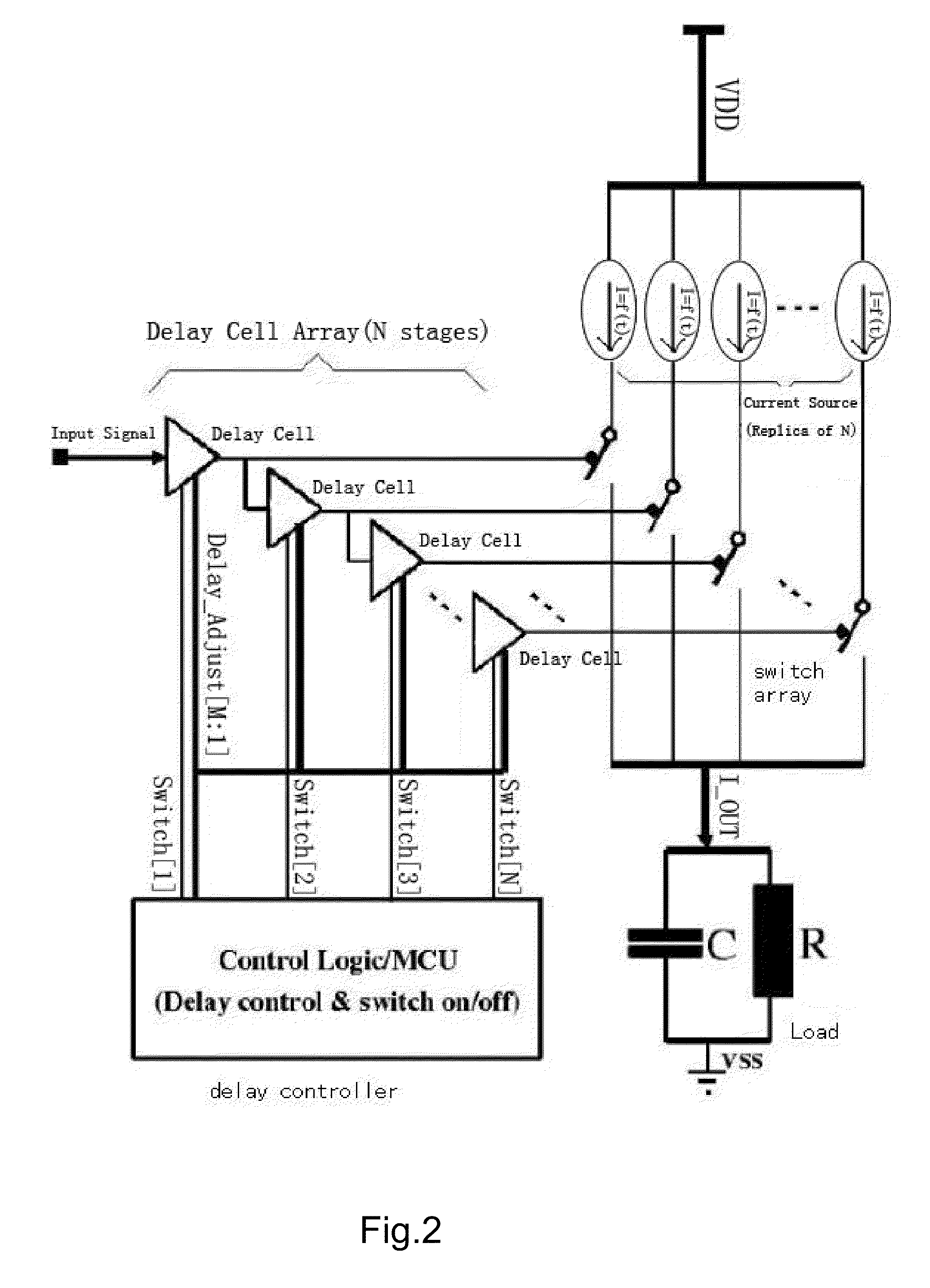
[0043]Referring to FIG. 2 of the drawings, a stage by stage delay current-summing slew rate controller is shown, which includes a delay controller, a delay cell array, a current source array, a switch array, a load. The delay cell array includes N delay cells, the switch array includes N switches, and the switch includes N current sources, wherein N>1. The delay controller is connected with the control ports of the delay cells respectively, and the delay cells are connected with the control terminal of the switches respectively. One of the connecting terminals of the switch is connected with the output end of the current source, and the other end of the connecting terminals of the switch is connected with one end of the load, and the other end of the load is connected to the ground.

[0044]The switches are connected with the current sources respectively in series.

[0045]The input ends of the current sources are connected with the power supply in parallel.

[0046]The current source is mir...

example ii

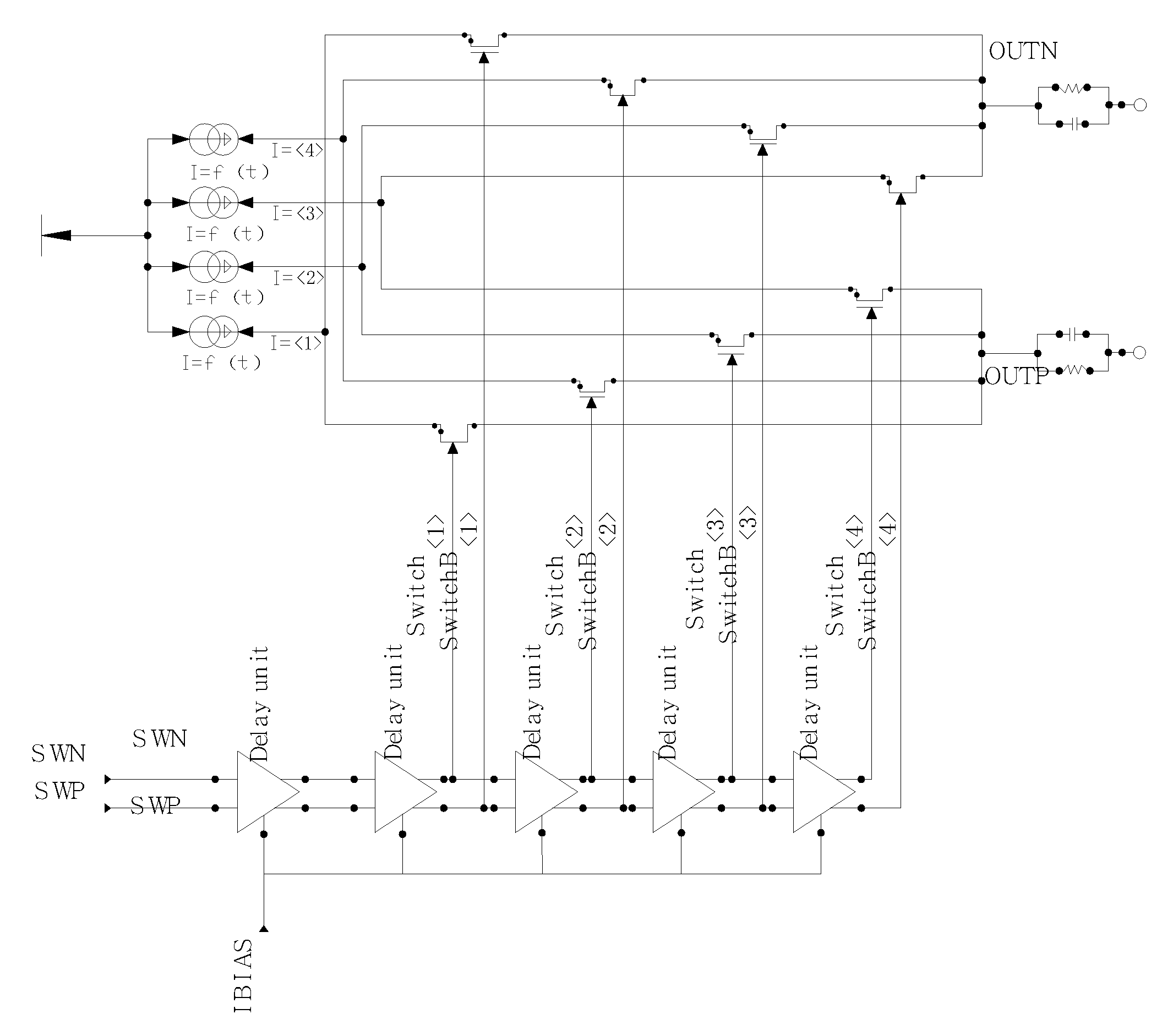
[0063]Referring to FIGS. 2 and 3 of the drawings, the present invention is applied to 4 stages delay current-summing slew rate controller, and the circuit is illustrated as follows.

[0064]The 4 stages delay current-summing slew rate controller includes a delay controller, a delay cell array with 4 delay cells, a current source array with 4 current sources, a switch array with 4 switches, and a load. The 4 switches of the switch array are connected with 4 current sources of the current source array respectively in series.

[0065]The delay controller is connected with the control ports of the 4 delay cells respectively, and the 4 delay cells are connected with the control terminal of the 4 switches of the switch array respectively. One of the connecting terminals of the switches are connected with the output end of the 4 current sources respectively, and the other end of the connecting terminals of the switches are connected with one end of the load, and the other end of the load is conn...

example iii

[0069]20 stages delay current-summing slew rate controller is used to depress the overshooting. The principle of the 20 stages delay current-summing slew rate controller is same with the 4 stages delay current-summing slew rate controller.

[0070]The work flow is illustrated as follows. Firstly, the delay cell array delays the input signal, the delay controller controls the delay time of each delay cell and gates the delay cell needed to work, then output signals of delay cells of the delay cell array control the corresponding switches of the switch array respectively, lastly the current sources of the current source array combine and output current under the control of the corresponding switches respectively. The output current drives the load to produce output voltage. During the working process, the output current and voltage are controllable, so that the output voltage slew rate can be controlled.


PUM


Abstract

A stage by stage delay current-summing slew rate controller includes a delay controller, a delay cell array, a current source array, a switch array, a load. The delay cell array includes N delay cells, the switch array includes N switches, and the switch includes N current sources, wherein N>1. The delay controller is connected with the control ports of the delay cells respectively, and the delay cells are connected with the control terminal of the switches respectively. One of the connecting terminals of the switch is connected with the output end of the current source, and the other end of the connecting terminals of the switch is connected with one end of the load, and the other end of the load is connected to the ground.

Description

BACKGROUND OF THE PRESENT INVENTION[0001]1. Field of Invention[0002]The present invention relates to a current source type voltage slew rate controller to drive capacitive load, and more particularly to a stage by stage delay current-summing slew rate controller.[0003]2. Description of Related Arts[0004]The circuit comprises a current drive and a load, wherein the load may be a capacitor, a parallel of a capacitor and a resistor, or other equivalent load, as shown in FIG. 1.[0005]Slew rate is to measure the changing rate of the voltage on the node. The mathematical expression is ∂V / ∂t.[0006]Generally, the slew rate SR=(I(t)−VOUT(t) / R) / C.[0007]I(t) is the transient current of the current source, Vout(t) is the transient voltage of the output node, R and C are the equivalent resistor and capacitor of the output load respectively. If R!=0, the slew rate (SR) will become small with the increasing of the output voltage, which is not good for the signal establishment. Conventionally, ther...

Claims


Application Information

Patent Timeline
Patent Type & Authority Applications(United States)
IPC IPC(8): H03H11/26
CPCG05F3/16
Inventor QUAN, YONGWU, GUOSHENG
Owner IPGOAL MICROELECTRONICS (SICHUAN) CO LTD
Why Eureka
Try Eureka