Combined intensity projection

a projection and intensity technology, applied in the field of medical image data visualization, can solve the problem that the information contained in these images does not take into account the location of pixels along the cast ray lin

Active Publication Date: 2010-03-04
KONINKLIJKE PHILIPS ELECTRONICS NV
View PDF2 Cites 26 Cited by
  • Summary
  • Abstract
  • Description
  • Claims
  • Application Information

AI Technical Summary

Benefits of technology

[0005]It would be advantageous to have a system for rendering an image based on a volumetric image data set, using a new rendering technique capable of providing further information about the visualized volumetric image data set.

Problems solved by technology

However, the information comprised in these images does not take into account the location of pixels along the cast ray.

Method used


Image

  • Combined intensity projection
  • Combined intensity projection
  • Combined intensity projection

Examples


Embodiment Construction

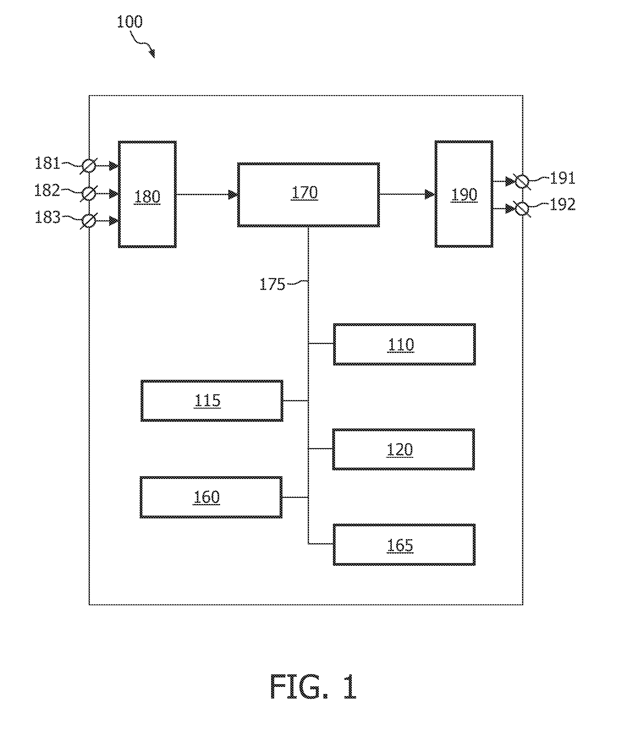
[0033]FIG. 1 schematically shows a block diagram of an exemplary embodiment of the system 100 for rendering an image based on a volumetric image data set, the system comprising:

[0034]a computation unit 110 for computing an initial pixel intensity of a pixel of the image defined by a corresponding voxel intensity of a corresponding voxel comprised in the volumetric image data set; and

[0035]an adjustment unit 120 for computing a final pixel intensity of the pixel, based on the initial pixel intensity and on a location of the corresponding voxel.

[0036]The exemplary embodiment of the system 100 further comprises the following optional units:

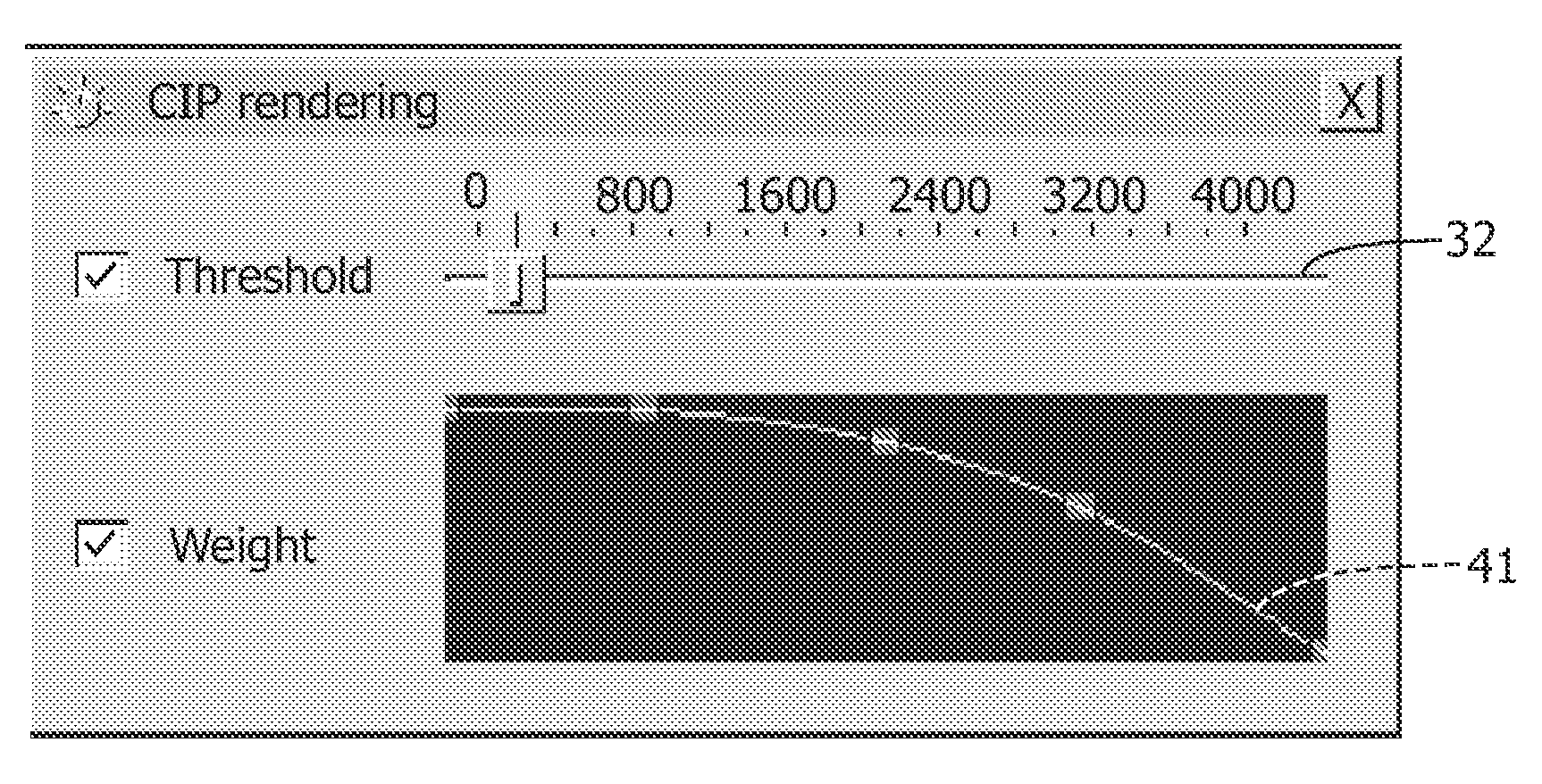
[0037]a weight unit 115 for computing a pixel weight based on the location of the corresponding voxel, the final pixel intensity being a product of the pixel intensity and the pixel weight;

[0038]a control unit 160 for controlling the workflow in the system 100;

[0039]a user interface 165 for communicating with a user of the system 100; and

[0040]a memo...


PUM


Abstract

The invention relates to a system (100) for rendering an image based on a volumetric image data set, the system comprising: a computation unit (110) for computing an initial pixel intensity of a pixel of the image, defined by a corresponding voxel intensity of a corresponding voxel comprised in the volumetric image data set; and an adjustment unit (120) for computing a final pixel intensity of the pixel, based on the initial pixel intensity and on a location of the corresponding voxel. Thus, the system of the invention enables new visualizations of volumetric image data sets. Advantageously, unlike a system using the VIP technique, which requires adjusting intensities of voxels comprised in the image data set, the system of the current invention is arranged to adjust intensities of pixels. This reduces the computational complexity of the rendering technique employed by the system relative to the computational complexity of the VIP technique.

Description

FIELD OF THE INVENTION[0001]The invention relates to the field of medical image data visualization and more specifically to visualization of volumetric medical image data.BACKGROUND OF THE INVENTION[0002]From a user point of view, volume visualization allows the user to quickly inspect the volumetric image data set and to select a region of interest to the user, such as a radiologist. The algorithms like maximum intensity projection (MIP), closest vessel projection (CVP) and average intensity projection (AIP) are based on ray casting. For each pixel of the displayed image a ray is cast from said pixel through the image data volume, typically a slab. The intensity of a pixel is computed based on the intensities of voxels along the cast ray. For MIP, the intensity of the pixel is the intensity of a voxel along the cast ray having the highest intensity. For CVP, the intensity of the pixel is the intensity of a first voxel along the cast ray having a maximum intensity, possibly a local ...

Claims


Application Information

Patent Timeline
Patent Type & Authority Applications(United States)
IPC IPC(8): G06T11/20G06T17/00G06T15/08
CPCG06T15/08G06T3/005G06T17/20G06T19/00
Inventor VISSER, CORNELIS PIETER
Owner KONINKLIJKE PHILIPS ELECTRONICS NV
Why Eureka
Try Eureka