Image Processing Apparatus, Imaging Apparatus, Solid-State Imaging Device, Image Processing Method and Program

a technology of image processing and imaging apparatus, applied in the direction of picture signal generators, solid-state device signal generators, television systems, etc., can solve the problems of difficult to correctly compensate the restoration of a long-time-exposure image saturation area, and difficult to generate a high-dynamic range imag

Inactive Publication Date: 2010-03-04
SONY SEMICON SOLUTIONS CORP
View PDF11 Cites 118 Cited by
  • Summary
  • Abstract
  • Description
  • Claims
  • Application Information

AI Technical Summary

Benefits of technology

[0023]With the solid-state imaging device, an array made up of the pixels having first spectral sensitivity, the pixels having second spectral sensitivity, and the pixels having third spectral sensitivity according to the first pixels, are a Bayer array inclined obliquely, and an array made up of the pixels having first spectral sensitivity, the pixels having second spectral sensitivity, and the pixels having third spectral sensitivity according to the second pixels, are a Bayer array inclined obliquely. Thus, there is provided an effect wherein imaging is executed by the solid-state imaging device wherein an array made up of the pixels having first spectral sensitivity, the pixels having second spectral sensitivity, and the pixels having third spectral sensitivity according to the first pixels is a Bayer array inclined obliquely, and an array made up of the pixels having first spectral sensitivity, the pixels having second spectral sensitivity, and the pixels having third spectral sensitivity according to the second pixels is a Bayer array inclined obliquely.
[0024]With the solid-state imaging device, on the upper side of a horizontal line made up of the first pixels and the second pixels arrayed alternately in the horizontal direction, a line transfer signal line that supplies a control signal used for executing readout by consecutive exposure within the predetermined period of time in the horizontal direction, and a line rest signal line, may be disposed and connected to the first pixels included in the horizontal line, and on the lower side of the horizontal line, a line transfer signal line that supplies a control signal used for executing readout sequentially by intermittent exposure within the predetermined period of time in the horizontal direction, and a line rest signal line, may be disposed and connected to the second pixels included in the horizontal line. Thus, there is provided an effect wherein imaging is executed by the solid-state imaging device wherein on the upper side of the horizontal line, a line transfer signal line that supplies a control signal used for executing readout by consecutive exposure within the predetermined period of time, and a line rest signal line are disposed and connected to the first pixels included in the horizontal line, and on the lower side of the horizontal line, a line transfer signal line that supplies a control sig

Problems solved by technology

However, in the case of using a short-time-exposure image to correct the camera shaking of a long-time-exposure image, it is difficult to correctly compensate the restoration of a saturation area of the long-time-exposure image from the short

Method used


Image

  • Image Processing Apparatus, Imaging Apparatus, Solid-State Imaging Device, Image Processing Method and Program
  • Image Processing Apparatus, Imaging Apparatus, Solid-State Imaging Device, Image Processing Method and Program
  • Image Processing Apparatus, Imaging Apparatus, Solid-State Imaging Device, Image Processing Method and Program

Examples


first embodiment

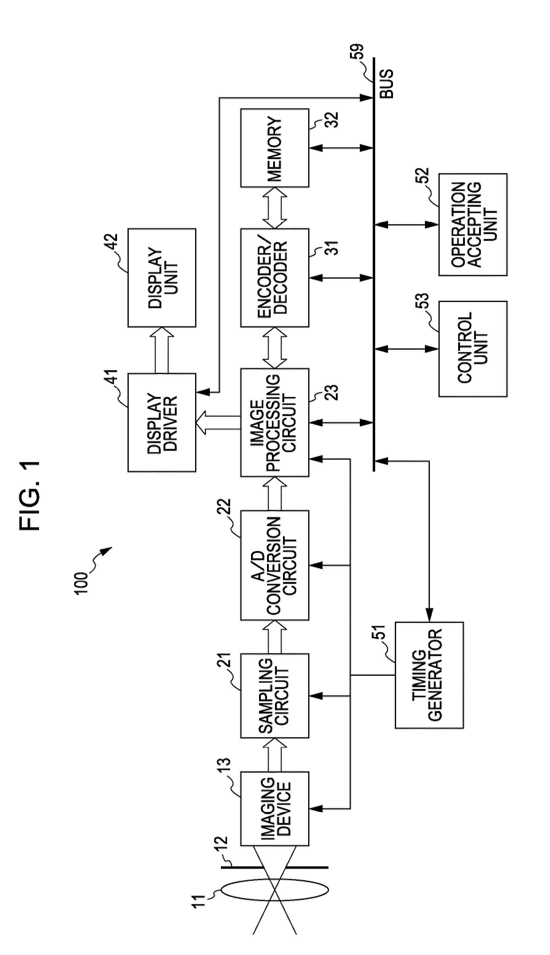
[0067]FIG. 1 is a block diagram illustrating an internal configuration example of an imaging apparatus 100 according to a first embodiment of the present invention. The imaging apparatus 100 includes a lens 11, a diaphragm 12, a solid-state imaging device 13, a sampling circuit 21, an A / D (Analog / Digital) conversion circuit 22, an image processing circuit 23, an encoder / decoder 31, and memory 32. Also, the imaging apparatus 100 includes a display driver 41, a display unit 42, a timing generator 51, an operation accepting unit 52, a control unit 53, and a bus 59. Note that the image processing circuit 23, the encoder / decoder 31, the memory 32, the display driver 41, the timing generator 51, the operation accepting unit 52, and the control unit 53 are connected mutually via the bus 59. The imaging apparatus 100 can be realized with, for example, a digital video camera (e.g., single unit camera recorder) which images a subject to generate a moving picture.

[0068]The lens 11 is a lens us...

second embodiment

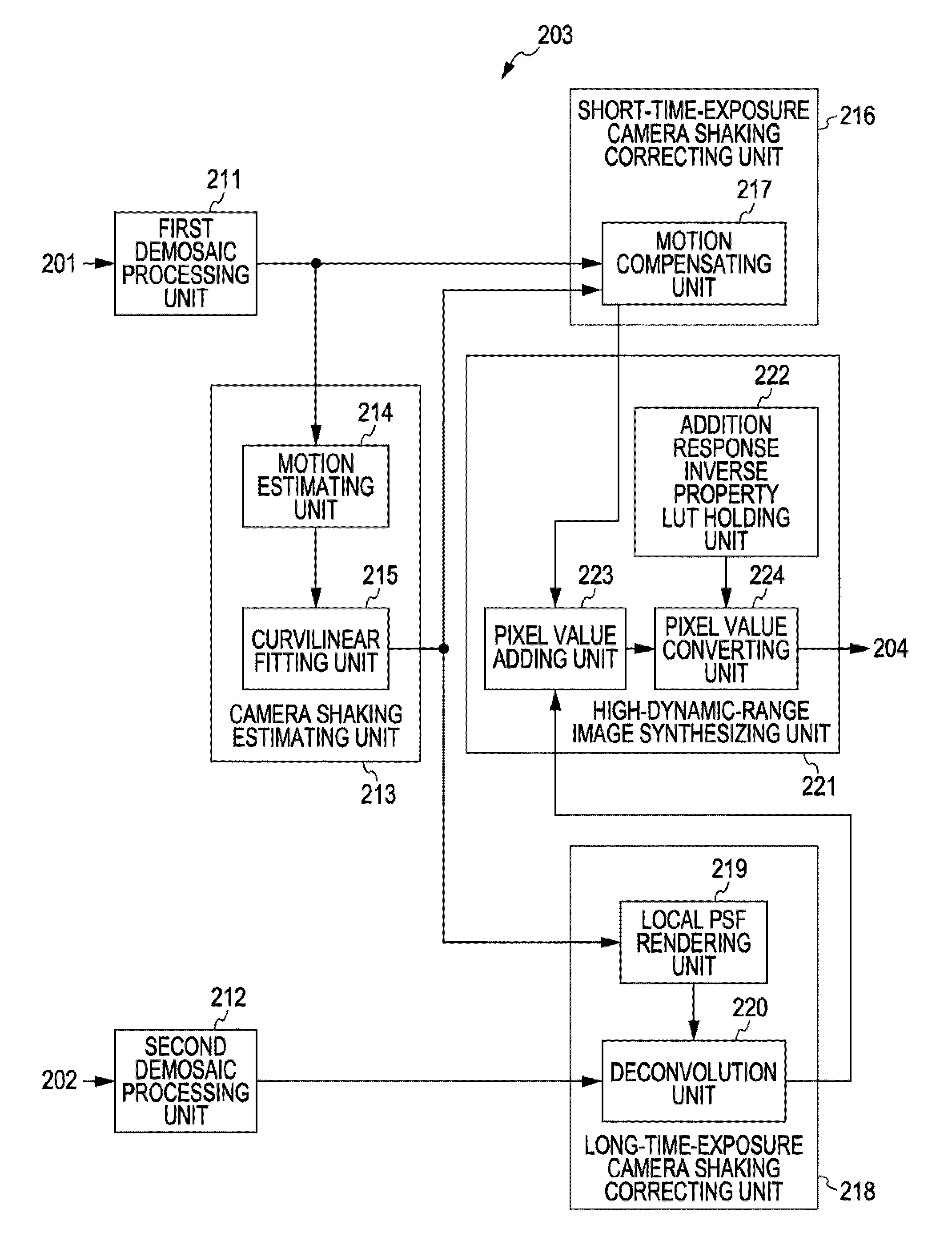
[0179]FIG. 21 is a block diagram illustrating a functional configuration example of an RGB image synthesizing unit 400 according to a second embodiment of the present invention. The RGB image synthesizing unit 400 is a modification of the RGB image synthesizing unit 203 shown in FIG. 10, and differs from the RGB image synthesizing unit 203 in that a camera shaking estimating unit 410 has been provided instead of the camera shaking estimating unit 213. Accordingly, description will be made mainly regarding the camera shaking estimating unit 410, and description of points which are the same as those in the RGB image synthesizing unit 203 shown in FIG. 10 will be omitted.

[0180]The camera shaking estimating unit 410 includes a motion estimating unit 411, a curvilinear fitting unit 412, a local PSF rendering unit 413, a motion compensating unit 414, a local PSF updating unit 415, and a camera shaking information updating unit 416.

[0181]The motion estimating unit 411 calculates the inter-...

third embodiment

[0219]FIG. 30 is a block diagram illustrating a functional configuration example of an RGB image synthesizing unit 500 according to a third embodiment of the present invention. The RGB image synthesizing unit 500 is a modification of the RGB image synthesizing unit 400 shown in FIG. 21, and differs from the RGB image synthesizing unit 400 in that a short-time-exposure camera shaking correcting unit 520 of a motion compensating unit 521 is used instead of the motion compensating unit 414 of the camera shaking estimating unit 410. Other configurations are. the same as with the RGB image synthesizing unit 400 shown in FIG. 21, so description will be omitted here. Note that a camera shaking estimating unit 510 is an example of the blurring estimating unit referred to in the Summary of the Invention, and the short-time-exposure camera shaking correcting unit 520 is an example of the short-time-exposure blurring correcting unit referred to in the Summary of the Invention.

[0220]Now, the RG...


PUM


Abstract

An image processing apparatus includes: a shaking estimating unit configured to estimate the shaking information of an image generated within a predetermined period of time; a short-time-exposure shaking correcting unit configured to correct the shaking of a plurality of short-time-exposure images generated due to intermittent exposure within the predetermined period of time based on the estimated shaking information; a long-time-exposure shaking correcting unit configured to correct the shaking of a long-time-exposure image generated due to consecutive exposure within the predetermined period of time based on the estimated shaking information; and an image synthesizing unit configured to synthesize the corrected short-time-exposure images and the corrected long-time-exposure image.

Description

BACKGROUND OF THE INVENTION[0001]1. Field of the Invention[0002]The present invention relates to an image processing apparatus, and specifically, relates to an image processing apparatus, an imaging apparatus, and a solid-state imaging device, which subject image data to an image process, and a processing method according thereto, and a program causing a computer to execute the method thereof.[0003]2. Description of the Related Art[0004]In recent years, CCD (Charge Coupled Device) sensors, CMOS (Complementary Metal Oxide Semiconductor) sensors, and so forth have come into widespread use as solid-state imaging devices which image a subject to generate image data. The dynamic range as to incident light of these solid-state imaging devices (i.e., the luminance range from a level wherein a signal is inextricable due to being lost in floor noise, to a saturation level) is improving steadily by progress of semiconductor technology. However, in reality, it is not so uncommon for incident l...

Claims


Application Information

Patent Timeline
IPC IPC(8): H04N5/228H04N5/232H04N5/235H04N5/335H04N5/351H04N5/353H04N5/355H04N5/374H04N9/07
CPCH04N5/23248H04N5/23254H04N5/23277H04N5/235H04N2209/046H04N5/35554H04N5/374H04N9/045H04N5/2355H04N23/6811H04N23/68H04N23/6845H04N23/70H04N23/741H04N25/583H04N25/76H04N23/843H04N25/134H04N25/589
Inventor MITSUNAGA, TOMOO
Owner SONY SEMICON SOLUTIONS CORP
Why Eureka
Try Eureka