Projection display apparatus and display method
a technology of projection display and display method, which is applied in the direction of projectors, color television details, instruments, etc., can solve the problems of incorrect keystone correction and achieve the effect of improving the accuracy of keystone correction
- Summary
- Abstract
- Description
- Claims
- Application Information
AI Technical Summary
Benefits of technology
Problems solved by technology
Method used
Image


Examples
first embodiment
A. First Embodiment
A-1. Configuration of Projector
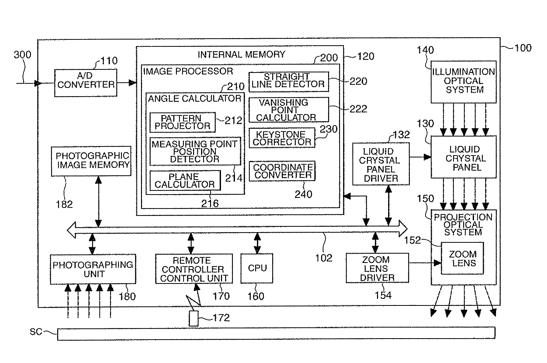
[0051]FIG. 1 is a block diagram schematically illustrating the configuration of a projector as a projection display device according to a first embodiment of the invention. The projector 100 projects an image beam indicating an image and displays the image (hereinafter, referred to as “display image”) on a projection plane such as a screen SC. In this embodiment, it is assumed that the screen SC is rectangular and has a black frame along its periphery.
[0052]The projector 100 includes an A / D converter 110, an internal memory 120, a liquid crystal panel 130, a liquid crystal panel driver 132, an illumination optical system 140, a projection optical system 150 having a zoom lens 152, a zoom lens driver 154, a CPU 160, a remote controller control unit 170, a remote controller 172, an image capturing unit 180, and a captured image memory 182. The elements of the projector 100 are connected to each other via a bus 102.
[0053]The A / D convert...
second embodiment
B. Second Embodiment
[0086]FIG. 11 is a block diagram schematically illustrating the configuration of a projector as a projection display apparatus according to a second embodiment of the invention. The projector 100a according to the second embodiment is different from the projector 100 according to the first embodiment shown in FIG. 1, in that the image processor 200a includes an absent side complementing section 250. The function of the absent side complementing section 250 will be described later with the description of the keystone correcting process to be described later. The other configurations of the projector 100a according to the second embodiment are the same as the projector 100 according to the first embodiment shown in FIG. 1. The absent side complementing section 250 corresponds to the line segment complementing section in the claims.
[0087]FIG. 12 is a flowchart illustrating a flow of the keystone correcting process performed by the projector 100a according to the sec...
modified example 1
C-1. Modified Example 1
[0099]In the second embodiment, the keystone correcting process of setting the area, which is surrounded by the frame sides of the screen SC detected from the captured image CI and the complementary sides CS for complementing the frame sides not detected as the target area TA and displaying an image in the area on the actual screen SC corresponding to the target area TA is performed. However, the keystone correcting method is not limited to it. FIG. 15 is a diagram illustrating a keystone correcting method according to a modified example. In the modified example shown in FIG. 15, the keystone correction is performed so that an image is displayed in a rectangular area having as one side a line segment on the screen SC corresponding to a line segment (hereinafter, referred to as “reference line segment RL”) detected or set in the captured image CI. Here, the reference line segment RL is detected or set arbitrarily and the line segment on the screen SC correspond...
PUM
 Abstract
Description
Claims
Application Information