High voltage EDLC cell and method for the manufacture thereof

a technology of edlc cells and capacitors, applied in the direction of identification means, physical/chemical process catalysts, instruments, etc., can solve the problems of large capacitors, large volume, high cost and cumbersome approaches, etc., and achieves a lower voltage standoff, lighter weight, and smaller volume

Inactive Publication Date: 2010-03-04
SYSTTIC POWER MFG LLC +1
View PDF100 Cites 11 Cited by
  • Summary
  • Abstract
  • Description
  • Claims
  • Application Information

AI Technical Summary

Benefits of technology

[0005]In accordance with the present invention, there is provided a single cell composite device designed to use a large number of individual cells in a single package, thus producing a “single cell” EDLC device with a higher voltage standoff than that of conventional EDLCs and that is lighter in weight, smaller in volume, and inherently free of complications that arise from cell balancing. The EDLC has a unit cell structure with alternately interleaved electrodes formed lithographically and a preformed separator disposed between the electrodes and impregnating an electrolyte therein. The unit cell has preformed electrodes with contained individual components specific to each electrode. The components are placed in precise intervals to develop a double layer effect. Extensions of individual blocks are also provided, containing additive capacitance, interfaced by allowing extra lengths of current collector to one of the electrodes and continuing forward with component placement or by sonic welding or by heat (spot) welding the extension pieces together.

Problems solved by technology

The capacitance of these devices is very large due to the effective surface of the activated carbon used to fabricate an EDLC and the spacing between the electrode and the molecules of the electrolyte that form the double layers.
For a specific application, a series-parallel configuration is often needed, but can include inherent problems.
This approach is frequently expensive and cumbersome.
The configurations are also large and heavy due to many individual cells used to form the composite structure.

Method used


Image

  • High voltage EDLC cell and method for the manufacture thereof
  • High voltage EDLC cell and method for the manufacture thereof
  • High voltage EDLC cell and method for the manufacture thereof

Examples


Embodiment Construction

[0016]The invention includes manufacturing steps for a single high voltage EDLC cell having characteristics associated with EDLC modular equipment associated with many subassembly components. An example capacitance of at least 58 farads and a stable voltage withstanding tolerance of 15 volts is used hereinbelow. It is not intended that this example be taken as a standard; rather, it should be understood this is an arbitrary choice to illustrate the concept. The methodology may be extended to virtually any other capacitance and voltage stack.

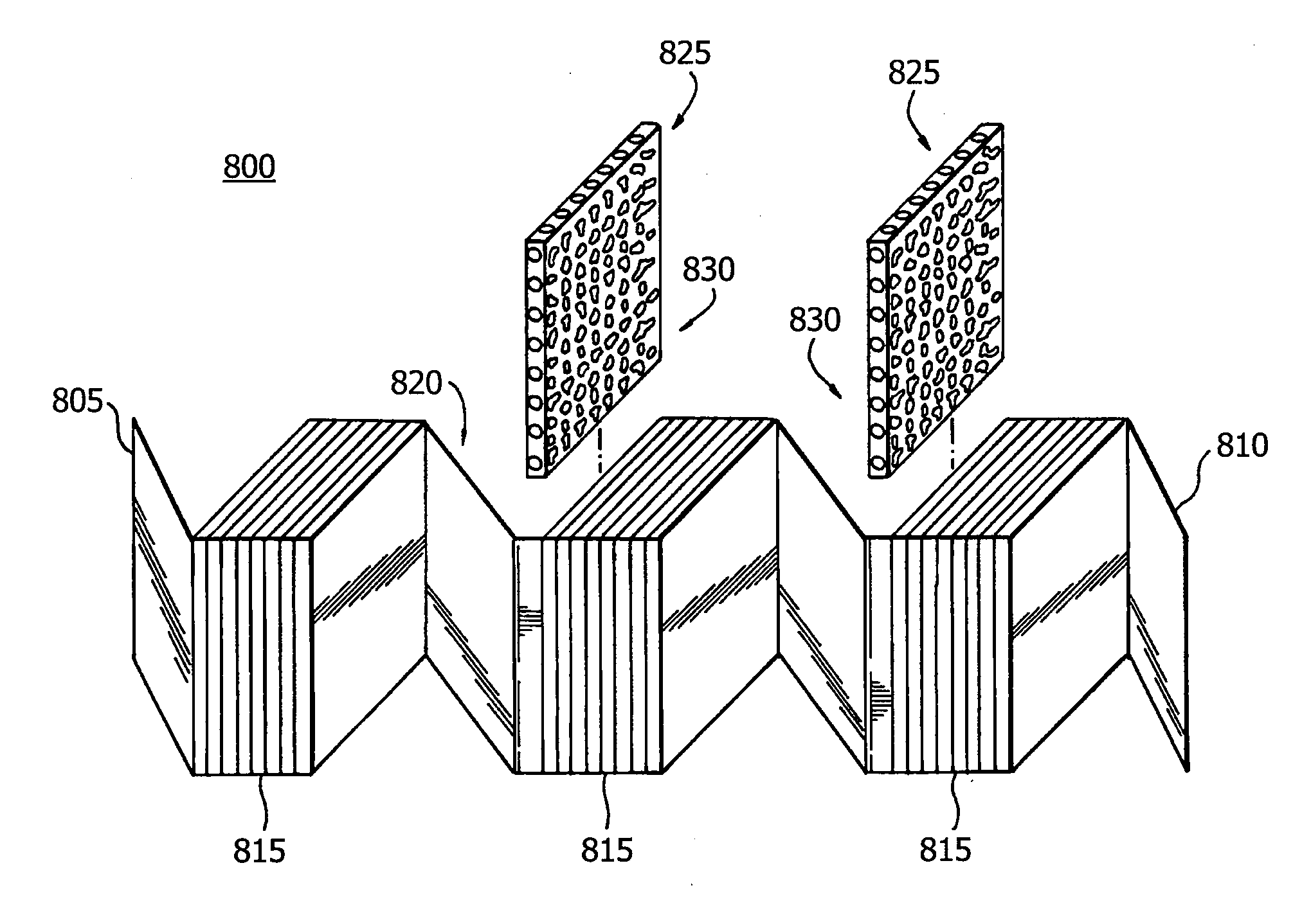
[0017]The electrode and electrode assembly structures are described in great detail because of their critical importance to the manufactured product. Other factors of importance are preparation, component design, component application sequence, electrode manipulation, block interface coupling, thermal component dissipaters, and packaging.

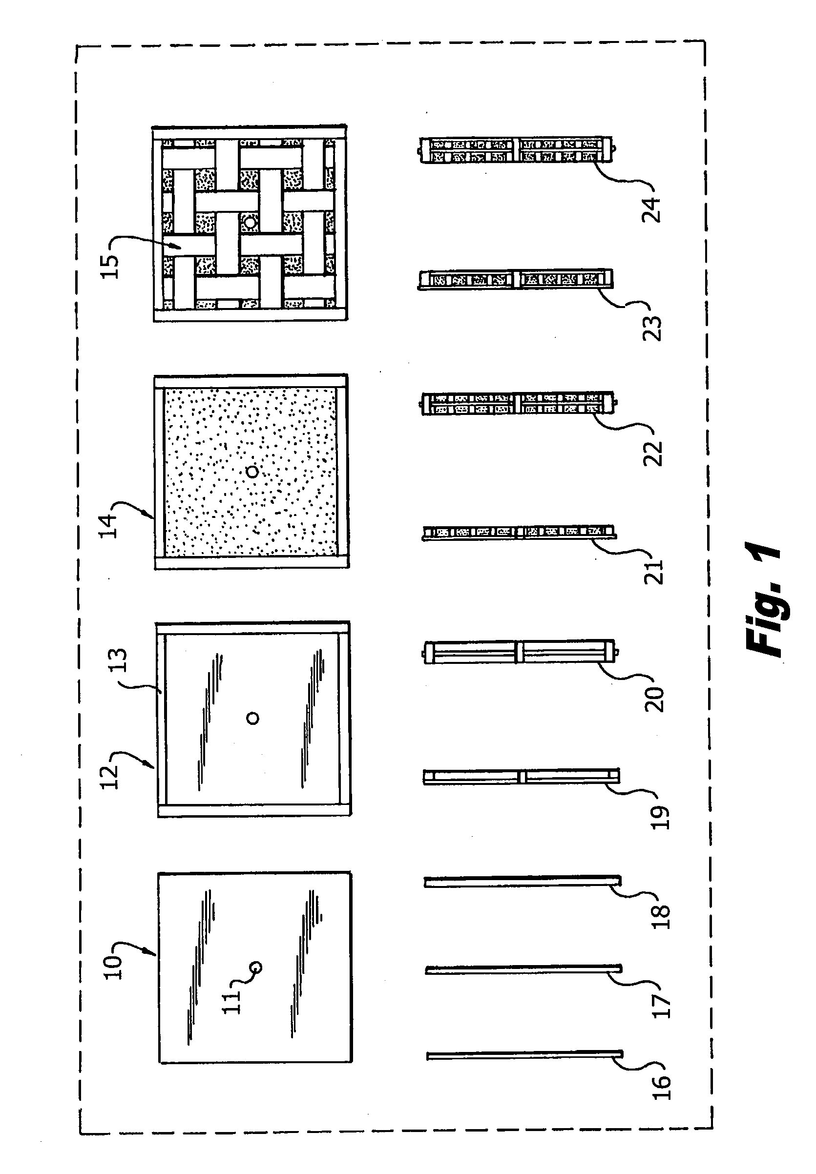
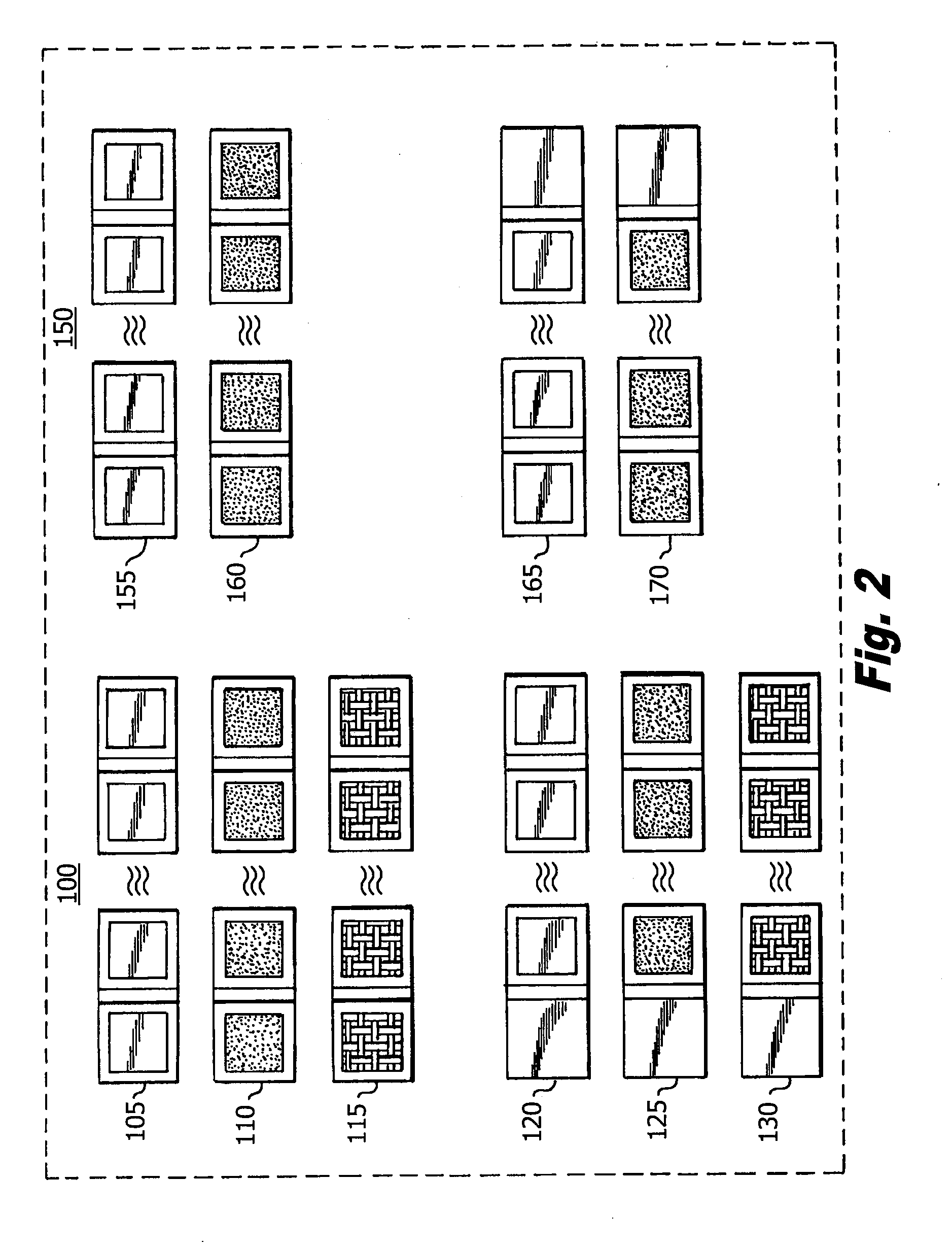
[0018]FIG. 1 shows the layer and component definition on the electrodes. Plan views of the manufacturing stage...


PUM


Abstract

An EDLC device in which the double layer capacitors themselves are produced lithographically. The resultant EDLC can be of any capacitance and voltage combination for a particular application. The entire lithographically formed entity can be housed in a single container and rated according to its capacitance and voltage standoff characteristics. Through material control processes, the electrochemical composites developed onto the current collector is unilaterally equalized, providing the desired distributed voltage standoffs, thus promoting the ability to design high voltage independent cells without the normal electronic balancing circuitry associated with multiple series-connected electrochemical cells.

Description

RELATED APPLICATIONS[0001]The present application is related to co-pending U.S. patent application Ser. No. 12 / 151,811 for ELECTRODE STRUCTURE FOR THE MANUFACTURE OF AN ELECTRIC DOUBLE LAYER CAPACITOR, incorporated by reference herein in its entirety.FIELD OF THE INVENTION[0002]The present invention relates to high voltage electrochemical double layer capacitors (EDLCs) and, more particularly, to a prototype design, manufacturing methods and materials to create electrodes for a high voltage EDLC, while maintaining high capacitance and low resistance thereof.BACKGROUND OF INVENTION[0003]An electrochemical double layer capacitor (EDLC) is an energy storage device consisting of two electrodes arranged in such a manner that one acts as the cathode and the other the anode, creating a structure that may be modeled as two capacitors in series. The device is characterized by a high power density whose value is dictated by the effective series resistance (ESR) of the device; the lower the ES...

Claims


Application Information

Patent Timeline
Patent Type & Authority Applications(United States)
IPC IPC(8): H01G9/155H01G11/86B01J21/00
CPCH01G11/86H01G11/04H01G11/26Y02E60/13H01G11/28H01G11/52Y10T156/1051Y10T156/1056B01J21/00B32B38/14B41F7/00G09F3/02G09F3/10H01G11/24H01G11/38
Inventor EILERTSEN, THOR E.
Owner SYSTTIC POWER MFG LLC
Why Eureka
Try Eureka