
Electric double layer capacitor

Inactive Publication Date: 2010-03-04
MEIDENSHA ELECTRIC MFG CO LTD
View PDF7 Cites 6 Cited by
  • Summary
  • Abstract
  • Description
  • Claims
  • Application Information

AI Technical Summary

Benefits of technology

[0012]It is therefore an object of the present invention which is given with the above-mentioned problem into consideration, to provide an electric double layer capacitor devised to suppress the entry of moisture into the depressurized inside of the capacitor even in the case where an enclosing member has a failure portion.
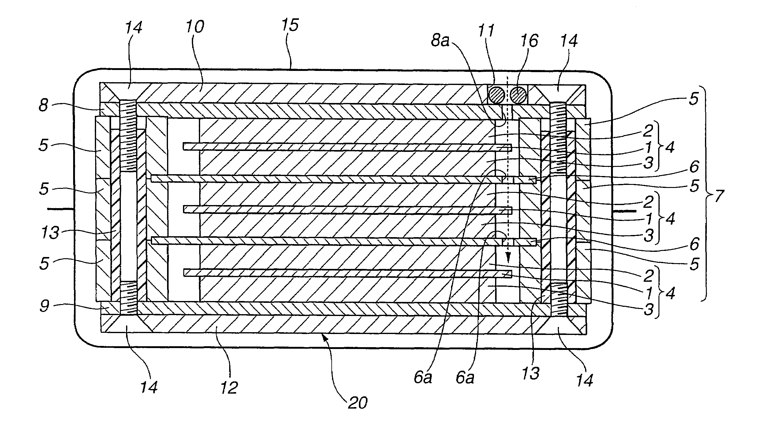
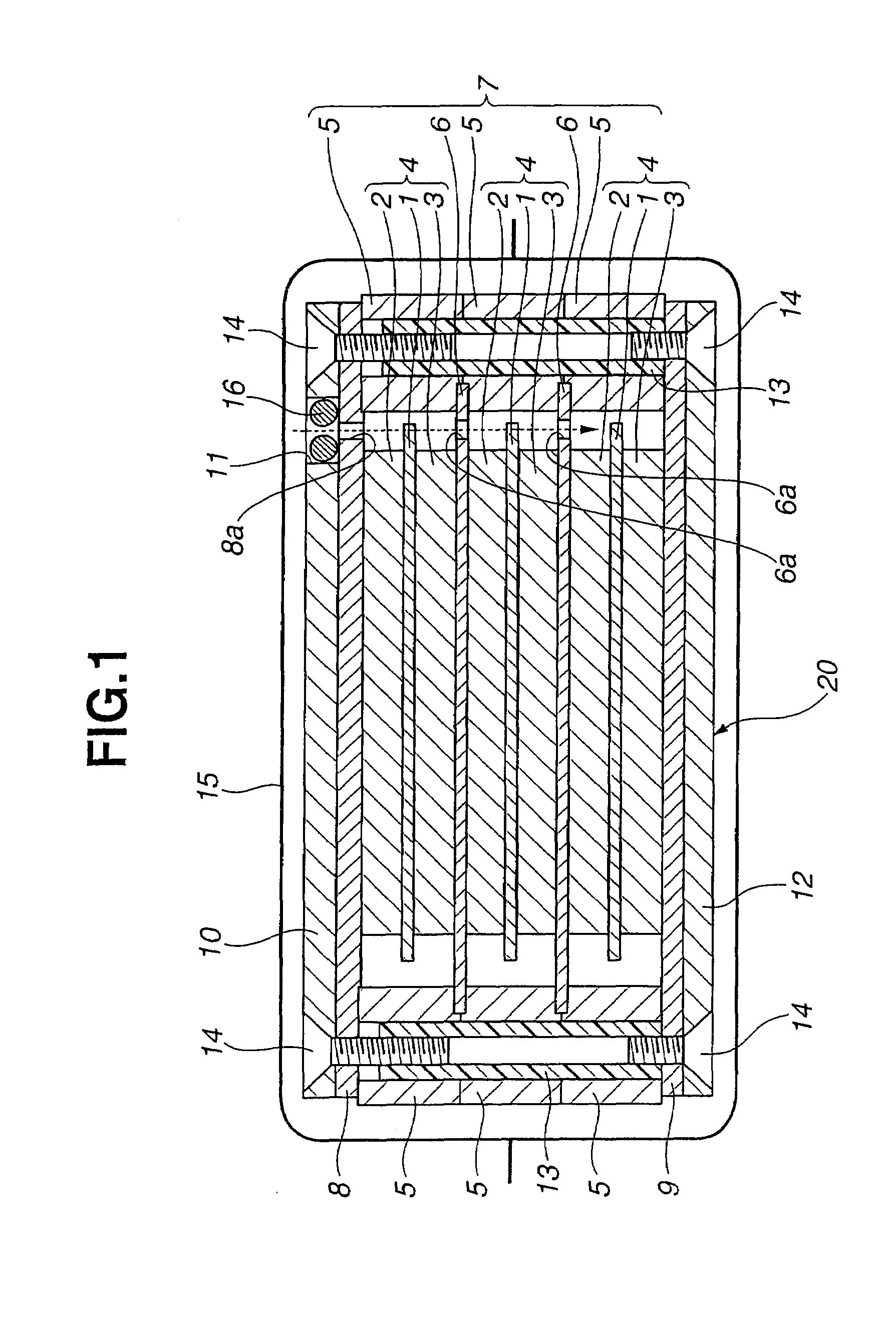
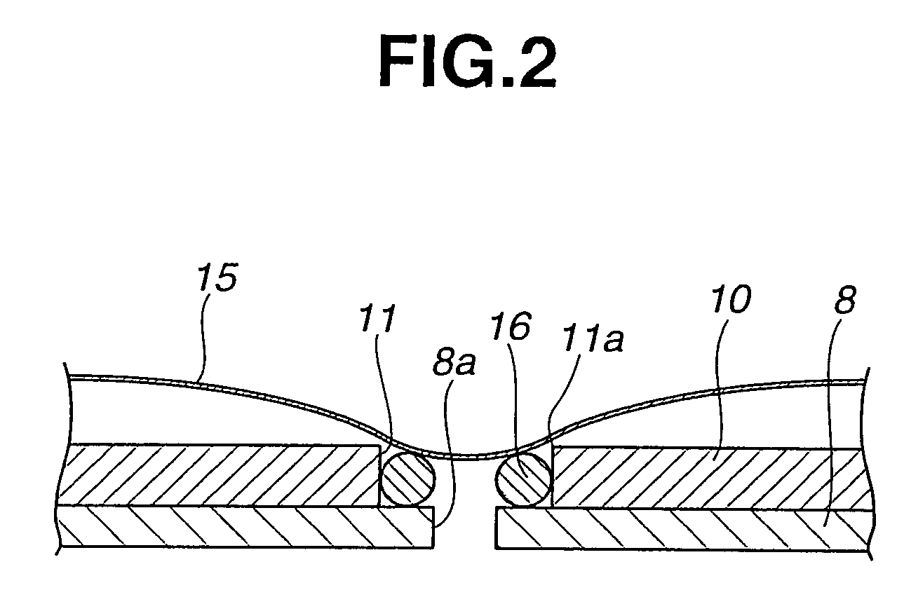
[0016]In the electric double layer capacitors according to the present invention, the plurality of cells each including activated-carbon electrodes disposed on both sides of the separator and the plurality of packing members each disposed at the outer periphery of the cell are stacked through the charge collector (s); the both end plates sandwiches the plurality of cells and the plurality of packing members through both collector electrodes; at least one of the end plates is formed with the inlet through which electrolytic solution is injected; the electric double layer capacitor is covered and sealed with the enclosing member; and the O-ring is disposed in the inlet, or the edge of the inlet is curved. Accordingly, the enclosing member becomes in surface-contact with the O-ring or the edge of the inlet, when exposing the capacitor at an atmospheric pressure after depressurizing the inside of the capacitor to vacuum state. Accordingly, even if the enclosing member has a failure at its welding portion located other than in the proximity of the inlet and thereby causes a vacuum leakage, the outside air which has entered between the enclosing member and the end plate can be prevented from promptly entering into the inside of the capacitor as compared with the case of an electric double layer capacitor of earlier technology in which an enclosing member is in point-contact with an edge of inlet of an end plate. Accordingly, the reprocessing can be conducted even after the sealing failure is found from its appearance.
[0017]In the electric double layer capacitors according to the present invention, there is provided the coating member which is disposed between the enclosing member and the end plate and which covers at least the inlet. Accordingly, the enclosing member can be prevented from being directly in contact with the edge portion of the inlet of the end plate. When the inside has been depressurized to the vacuum state, the outside air between the enclosing member and the end plate can be prevented more reliably from promptly entering into the inside of the capacitor. Accordingly, even after detecting a sealing failure from its appearance, the reprocessing can be conducted.
[0018]In the electric double layer capacitor according to the present invention, the coating member is a polyethylene terephthalate film. Accordingly in addition to the above-mentioned operations and advantages, even if the outside air enters the inside of the enclosing member when the inside of the capacitor has been depressurized to vacuum state; the polyethylene terephthalate film itself is thin and flexible, and therefore there is no possibility that the sealing between the polyethylene terephthalate film and the end plate at a position corresponding to the inlet is removed by the external pressure and the outside air enters the inside of the capacitor. As the result, even after finding a sealing failure of the enclosing member from its appearance, the reprocessing can be carried out.

Problems solved by technology

However, there are cases where a large amount of moisture enough to disable the reprocessing enters the inside of the capacitor.

Method used


Image

  • Electric double layer capacitor
  • Electric double layer capacitor
  • Electric double layer capacitor

Examples


first embodiment

[0025]An electric double layer capacitor according to a first embodiment of the present invention will now be explained by use of the drawings.

[0026]FIG. 1 is a schematic sectional view showing the electric double layer capacitor according to the first embodiment of the present invention. FIG. 2 is an explanatory view showing a condition where an inside of the electric double layer capacitor according to the first embodiment of the present invention has been depressurized.

[0027]The electric double layer capacitor 20 according to the first embodiment of the present invention includes cells 4 as shown in FIG. 1. Each of the cells 4 includes an ion-permeable separator 1 and activated-carbon electrodes 2 and 3 disposed respectively at both sides of the separator 1. At an outer periphery of this cell 4, a packing member (packing) 5 is disposed. A plurality of packing members 5 and cells 4 are layered or stacked (e.g., in three layers in this drawing) through a charge collector(s) 6, to f...

second embodiment

[0034]An electric double layer capacitor according to a second embodiment of the present invention will now be explained concretely by use of the drawings.

[0035]FIG. 3 is a schematic sectional view showing the electric double layer capacitor according to the second embodiment of the present invention. The electric double layer capacitor according to the second embodiment of the present invention includes the same members as those of the above-mentioned electric double layer capacitor according to the first embodiment of the present invention, and further includes a coating member (covering member) disposed between the end plate and the aluminum laminate film. Hence, the same members as those of the above-mentioned electric double layer capacitor according to the first embodiment of the present invention are given same reference signs, and the explanations thereof will be omitted.

[0036]The electric double layer capacitor 30 according to the second embodiment of the present invention ...


PUM


Abstract

It is disclosed that an electric double layer capacitor includes a plurality of cells each including activated-carbon electrodes disposed on both sides of a separator; a plurality of packing members each disposed at an outer periphery of the cell, each of the plurality of cells and the plurality of packing members being stacked through a charge collector; and both end plates sandwiching the plurality of cells and the plurality of packing members through both collector electrodes, at least one of the end plates being formed with an inlet through which an electrolytic solution is injected. Moreover, the electric double layer capacitor is covered and sealed with an enclosing member. Moreover, the electric double layer capacitor includes an O-ring disposed in the inlet, or alternatively, an edge of the inlet is curved.

Description

TECHNICAL FIELD[0001]The present invention relates to an electric double layer capacitor.BACKGROUND ART[0002]An electric double layer capacitor operates on the principle that an electricity is stored by allowing a physisorption of anion and cation included in an electrolyte, on positive-pole and negative-pole surfaces of polarizable electrodes.[0003]For example, a bipolar-type electric double layer capacitor (hereinafter referred to as capacitor) 100 includes a plurality of cells 104 each of which includes an ion-permeable separator 101 and activated-carbon electrodes 102 and 103 disposed respectively at both sides of the separator 101, as shown in FIG. 4. The capacitor 100 is formed by providing a charge collector 105 between the adjacent cells 104 and by layering or stacking the plurality of cells 104. The activated-carbon electrodes 102 and 103 are impregnated with an electrolytic solution. A packing member 106 is disposed at an outer peripheral portion of the cell 104 so as not ...

Claims


Application Information

Patent Timeline
IPC IPC(8): H01G9/155H01G11/00H01G11/10H01G11/12H01G11/66H01G11/78H01G11/82H01G11/84
CPCH01G9/08Y02E60/13H01G9/155H01G11/12H01G11/78H01G11/80
Inventor HORIKOSHI, RON
Owner MEIDENSHA ELECTRIC MFG CO LTD
Learn More