Shear dowel assembly

a technology of diamond dowels and assembly parts, which is applied in the direction of roadways, paving details, roads, etc., can solve the problems of random and unsightly cracking, need for joints, and the performance of concrete floors are affected, so as to increase the differential movement of adjacent concrete slabs, and accelerate the load carrying capacity of diamond dowels

Inactive Publication Date: 2010-03-04
PCLN HLDG
View PDF15 Cites 27 Cited by
  • Summary
  • Abstract
  • Description
  • Claims
  • Application Information

AI Technical Summary

Benefits of technology

[0055]It may be seen that the arrangement and construction of the shear dowel assembly allows for increased differential movement of the adjacent concrete slabs as the joint gap between the adjacent concrete slabs increases, and furthermore the load carrying capacity of the shear dowel is maintained due to it being of a constant cross section.
[0056]That is, as the joint gap develops its width, the shear dowel is pulled out of the dowel sheath, and the further the shear dowel is pulled out, the further the distance between the side edges of the shear dowel and the tapered sides of the dowel sheath, thus allowing for increased differential movement of the adjacent concrete slabs as the joint gap increases.
[0057]This is a m...

Problems solved by technology

The use of concrete introduces a widespread problem in the performance of these floors, since concrete is a material that shrinks slightly during the curing process.
If joints are not included in floors on a planned basis, then random and unsightly cracking will take place.
The need for joints creates a problem for designers because the design for the thickness of the concrete assumes that the concrete is continuous, and any location at which the concrete terminates becomes a location of reduced strength in the floor.
The design of shear dowels is a complex process, since several design factors must be considered, and the governing factors may change depending on how wide the concrete joint becomes.
Traditionally, round steel bars were used, however, these have a disadvantage in practical use.
Round dowels restrain this movement since they are tightly encased in concrete, and this restraint can contribute to cracking in the concrete, which is undesirable.
However, use of these steel dowel bars only allowed for very small amounts of differential movement of adjacent concrete slabs, and so their use is limited.
This occurs over a relatively short length of steel, so, if the dowel bar is also narrow, then a low effective contact area results, and stresses become high, which may govern the dowel capacity.
That is, as concrete shrinkage opens t...

Method used


Image

  • Shear dowel assembly
  • Shear dowel assembly
  • Shear dowel assembly

Examples


Embodiment Construction

[0076]The description of a preferred form of the invention to be provided herein, with reference to the accompanying drawings, is given purely by way of example and is not to be taken in any way as limiting the scope or extent of the invention.

DRAWINGS

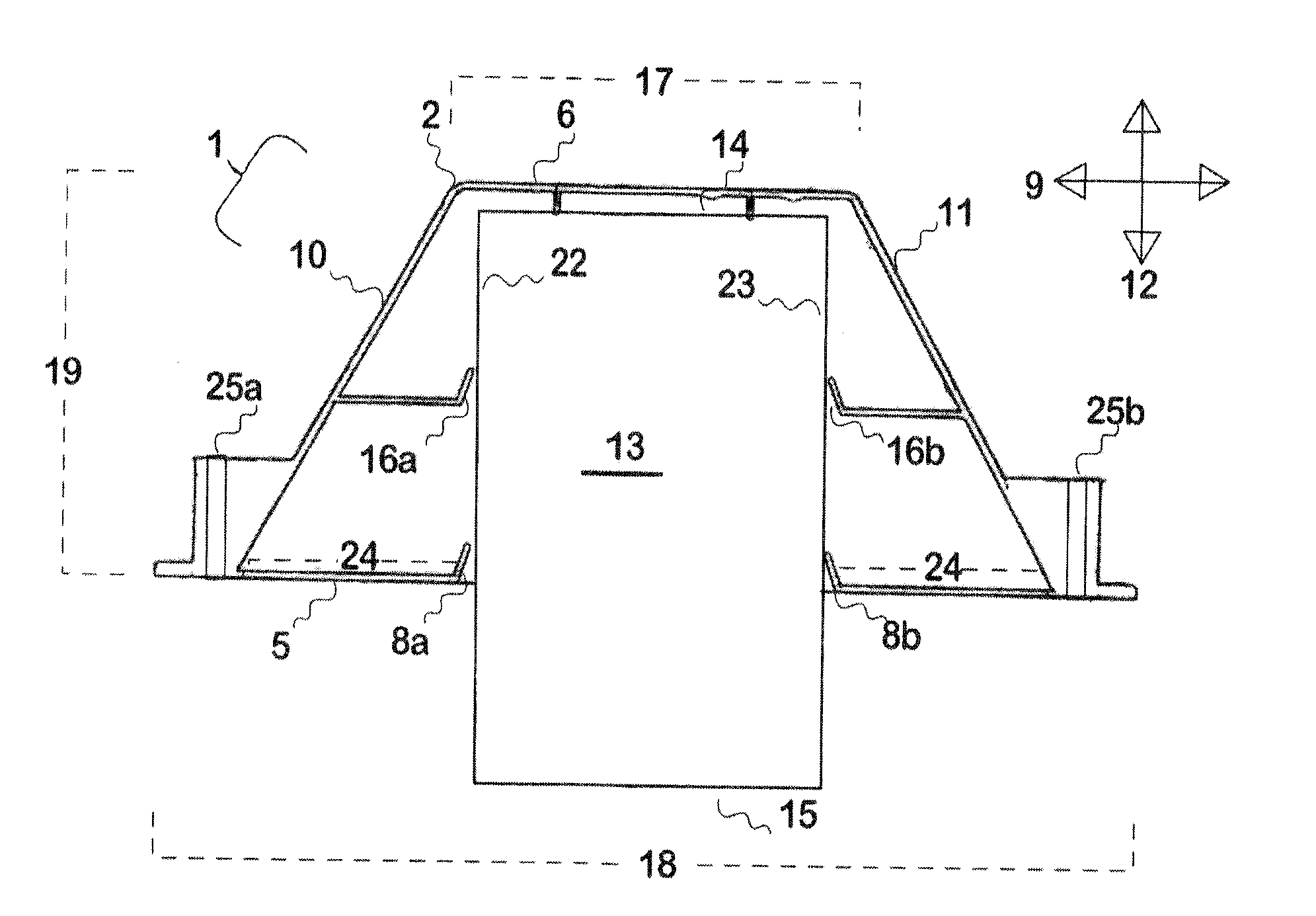
[0077]FIG. 1: is a cutaway plan view of one possible embodiment of a shear dowel assembly of the present invention,

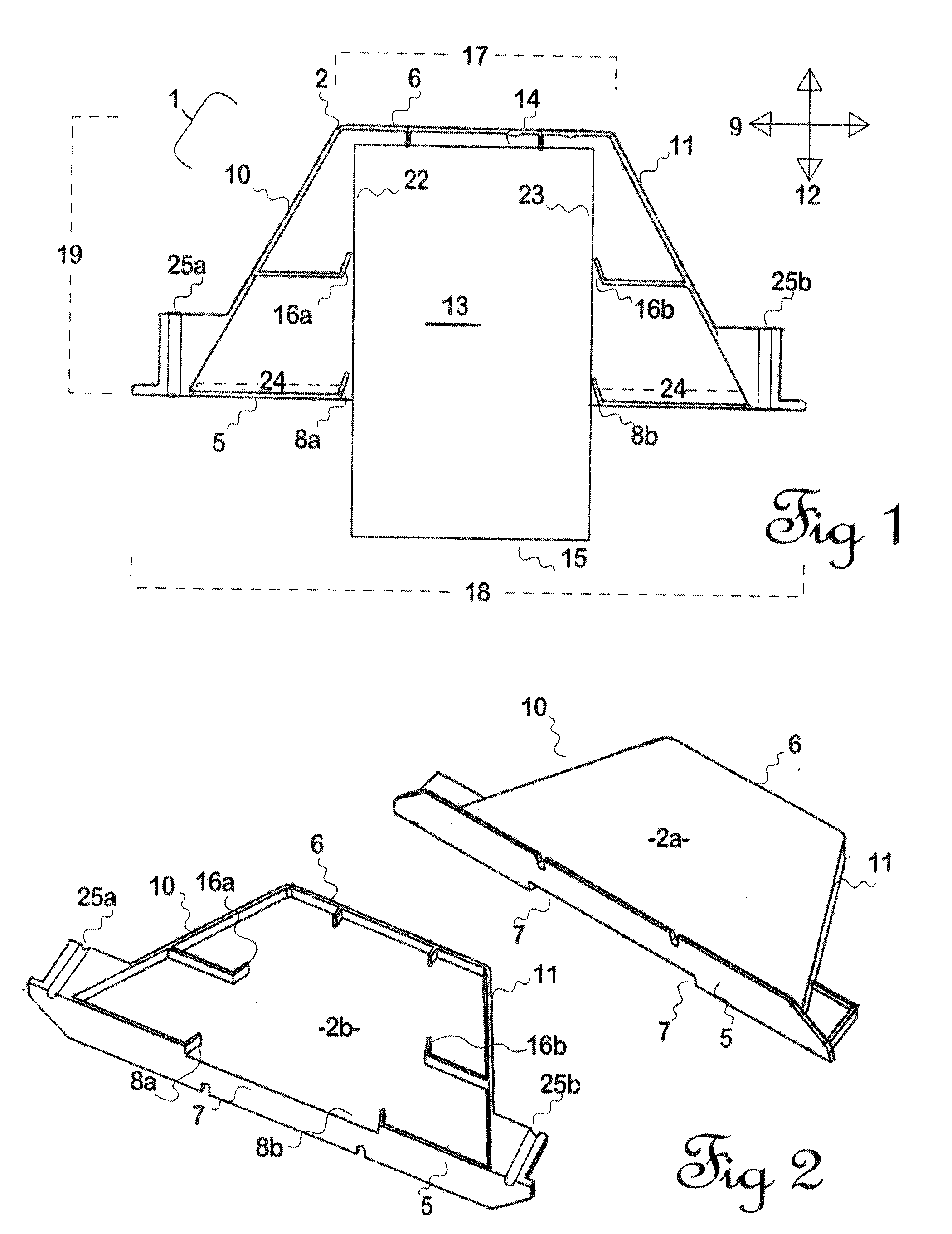
[0078]FIG. 2: is a perspective, exploded view, of the dowel sheath illustrated in FIG. 1.

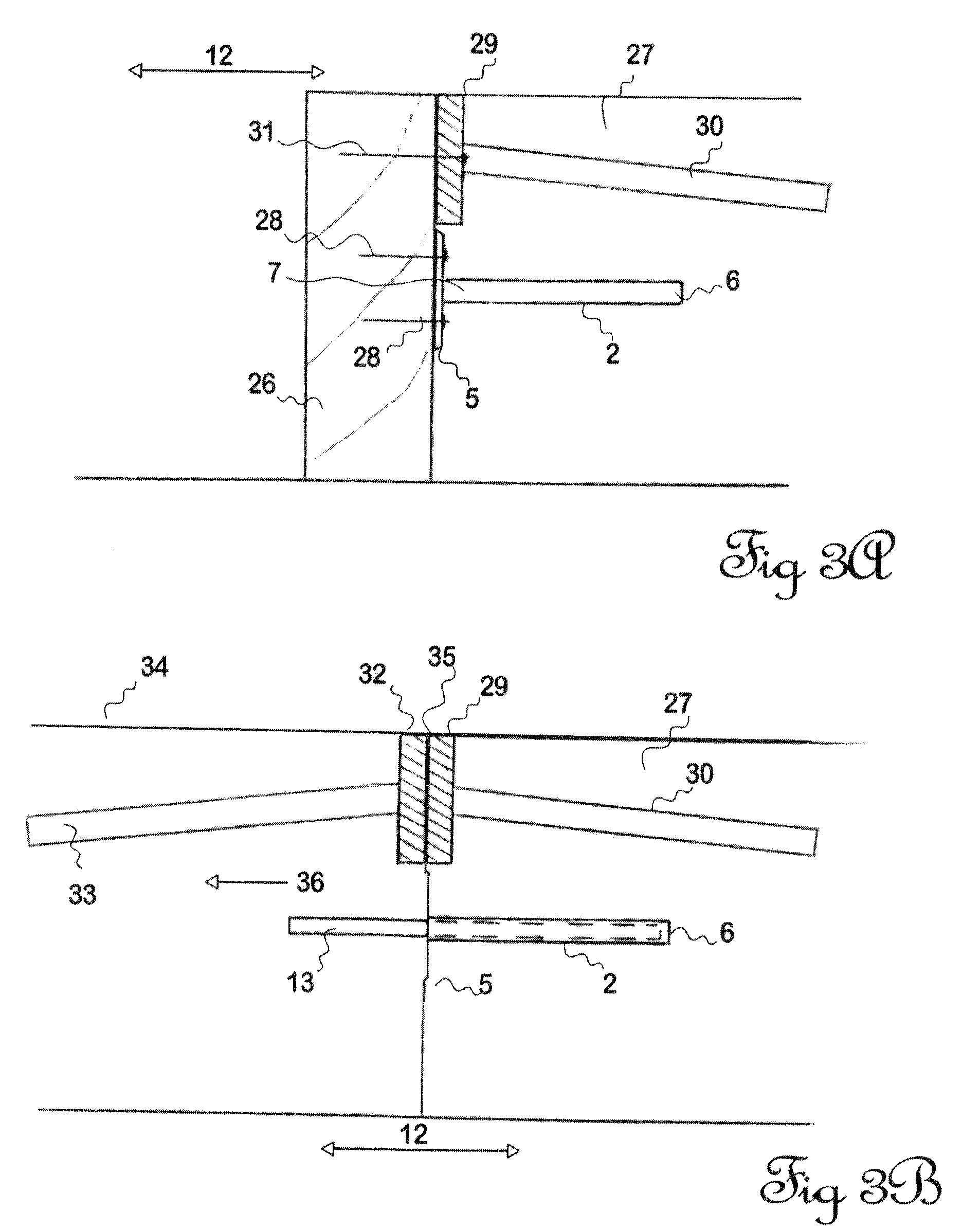
[0079]FIG. 3a: is a cross-sectional view of a joint to be formed between two adjacent concrete slabs, utilising a timber form and the embodiment of the invention as illustrated in FIG. 1,

[0080]FIG. 3b: is a cross-sectional view of the embodiment illustrated in FIG. 3a, after the pour of the second concrete slab, and

[0081]FIG. 4: is a cross-sectional view of a joint formed between two adjacent concrete slabs, utilising a metal form and the embodiment of the invention as illustrated in FIG. 1.

DESCRIPTION OF PREFERRED EMBODIMENTS

[0082]Wit...


PUM


Abstract

This invention relates to a shear dowel assembly for distributing loads between adjacent concrete slabs, separated by a joint. The shear dowel assembly includes a dowel sheath having a front face and a rear face. The rear face of the dowel sheath is imbedded within the first concrete slab, whereas the front face is left substantially flush with the side of said first concrete slab. The front face also has a portion defining an opening therein. There is also provided a shear dowel adapted to be inserted into the opening in the dowel sheath, with a first end of the shear dowel abutting the rear face of the dowel sheath, and a second end of the shear dowel extending out from the opening in the dowel sheath, whereby the shear dowel may be embedded within a second adjacent concrete slab to be poured. The shear dowel has a width of constant cross section, and is preferably trapezoidal (or in the shape of a trapezium) in plan view. The shear dowel assembly allows for increased differential movement of the adjacent concrete slabs, as the joint gap between the concrete slabs increases, whilst retaining the load carrying capacity of the shear dowel at all times.

Description

FIELD[0001]This invention relates to an improved shear dowel assembly, for use in relation to construction using concrete. The invention may be particularly suitable for use in distributing loads between adjacent concrete slabs, separated by a joint, and especially during the curing, shrinking and / or thermal expansion of the adjacent concrete slabs.BACKGROUND[0002]A majority of the floors in industrial buildings at ground level are constructed in concrete. The use of concrete introduces a widespread problem in the performance of these floors, since concrete is a material that shrinks slightly during the curing process.[0003]Concrete shrinkage is typically about 8 one thousandths of an inch in a one foot length, which, in a section of concrete 100 feet long, will give total shrinkage of about 0.8 inches[0004]The shrinkage in the concrete requires designers and constructors to install joints or breaks in the concrete, to establish locations at which the concrete shrinkage can be taken...

Claims


Application Information

Patent Timeline
IPC IPC(8): E01C11/14
CPCE01C11/14
Inventor MAYO, LINDSAY NEILWICKINS, CARL BERNARD
Owner PCLN HLDG
Why Eureka
Try Eureka