Storage shelf

a storage shelf and shelf body technology, applied in the field of storage shelves, can solve the problems of inability to support the object to be vibration-isolated, the object may be subject to vibration transmission, etc., and achieve the effects of reducing vibration, reducing vibration, and maintaining load-carrying capacity

Inactive Publication Date: 2016-05-19
MURATA MASCH LTD
View PDF2 Cites 0 Cited by
  • Summary
  • Abstract
  • Description
  • Claims
  • Application Information

AI Technical Summary

Benefits of technology

[0007]Preferred embodiments of the present invention provide a storage shelf that reduces vibration while maintaining load-carrying capacity.
[0010]In one preferred embodiment of the present invention, the object may be a front-opening unified pod (FOUP) configured to accommodate therein wafers. The placement unit may include a third elastic body arranged between the frame and the shelf plate and having a rigidity higher than those of the first and the second elastic bodies. The third elastic body may be arranged on a side where a lid of the FOUP is positioned when the FOUP is placed on the shelf plate. In general, the side near the lid is heavier than other sides in the FOUP. This shifts the center of gravity of the FOUP toward the side near the lid. In view of this, in the storage shelf, the third elastic body having the rigidity higher than those of the first and the second elastic bodies is arranged on the side where the lid of the FOUP is positioned. This enables the storage shelf to reduce vibration and also prevent the FOUP from tilting.
[0011]In one preferred embodiment of the present invention, the frame unit may include a pair of beam members facing each other. The frame may be disposed over the pair of beam members. The frame may include a concave portion positioned between the pair of beam members and including a base portion extending in an opposing direction of the pair of beam members and a pair of raised portions that are raised from both ends of the base portion, and include overhanging portions that overhang from ends of the raised portions and are mounted on the beam members each with the first elastic body interposed therebetween. The second elastic body may be arranged on the concave portion of the frame. This arrangement enables the storage shelf to prevent the position of the shelf plate from becoming higher even when the first elastic body and the second elastic body are provided in series. Thus, in the storage shelf, space in the height direction of the placement unit is able to be saved.
[0012]In one preferred embodiment of the present invention, the frame unit may be secured to a rail of a traveling vehicle or to a supporting member supporting the rail. This arrangement enables the storage shelf to simplify the configuration without the need to provide an additional member for supporting the storage shelf.
[0014]In this storage shelf, the placement unit is arranged on the frame unit secured to the rail or the supporting member with the elastic body interposed therebetween. Accordingly, vibration that occurs at the rail when the traveling vehicle travels is able to be prevented from being transmitted from the frame unit to the placement unit, such that the vibration of the object is reduced.
[0015]Preferred embodiments of the present invention reduce vibration while maintaining load-carrying capacity.

Problems solved by technology

Examples of the storage shelf include one provided along a track of an overhead carrier and one suspended from a ceiling, such storage shelves may be subjected to vibration transmitted when the overhead carrier travels.
However, when the spring constant of the vibration-isolating member is set lower, a problem may occur in that the object to be vibration-isolated cannot be supported while the elasticity of the vibration-isolating member is maintained.

Method used


Image

  • Storage shelf
  • Storage shelf
  • Storage shelf

Examples


first preferred embodiment

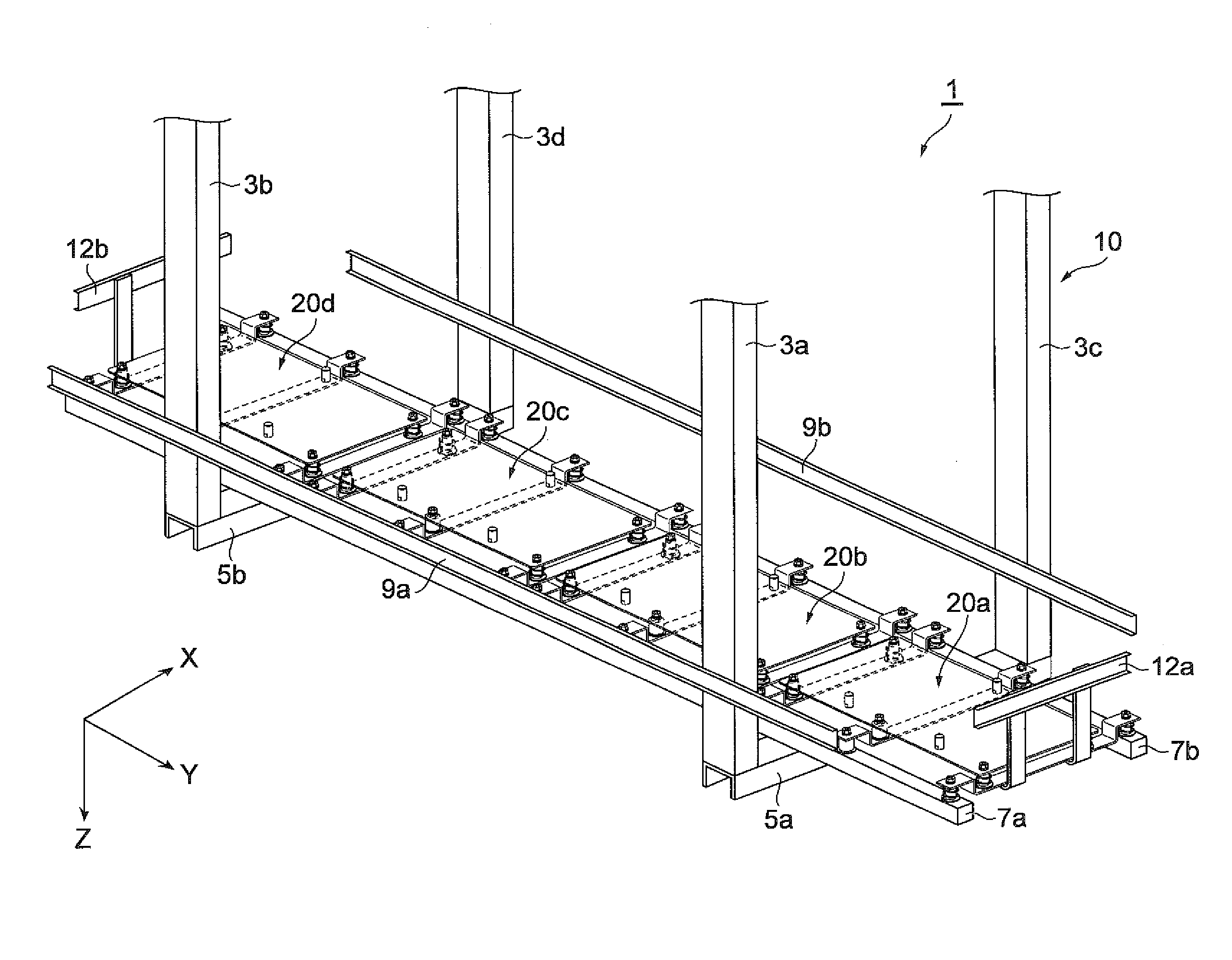
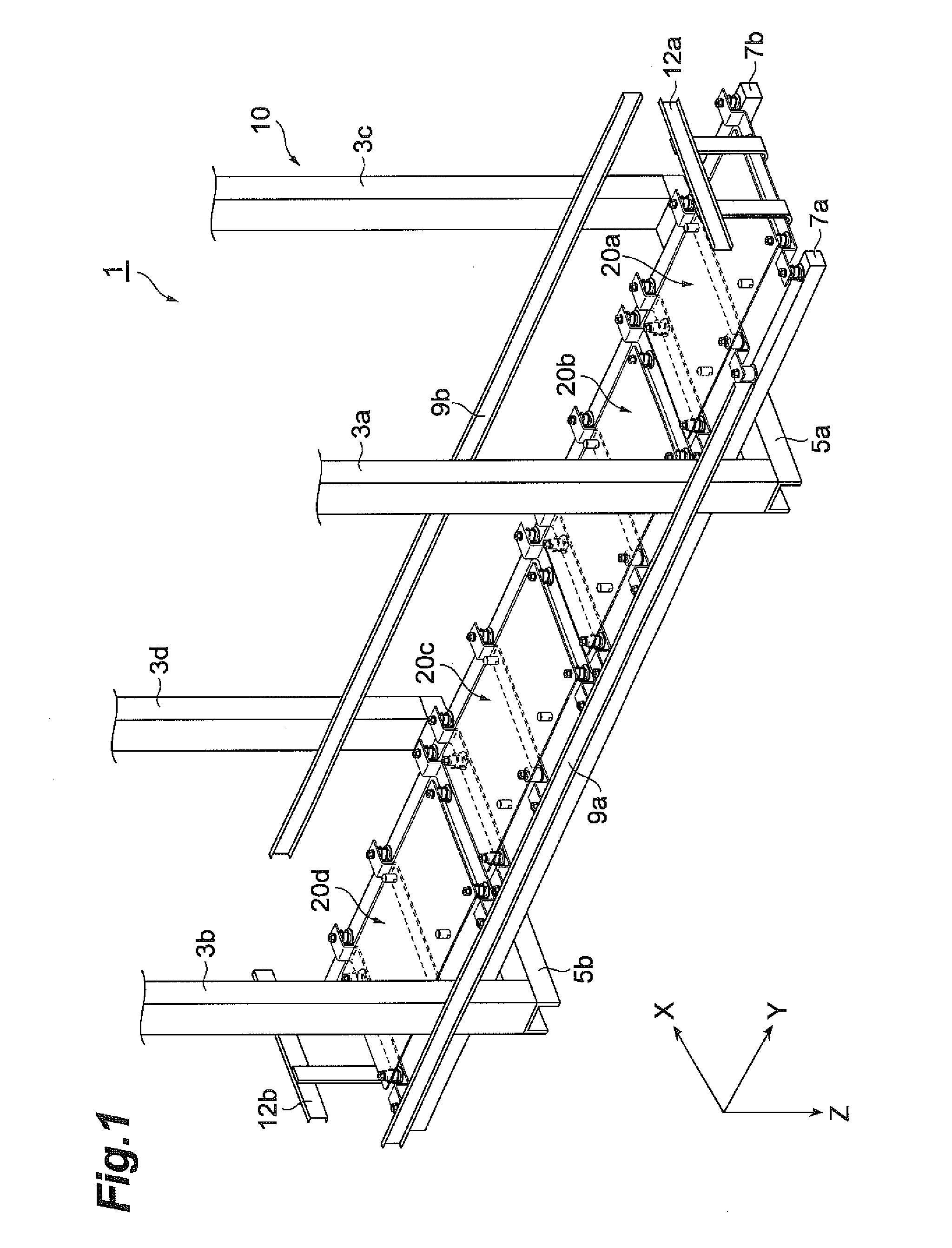
[0023]FIG. 1 is a perspective view illustrating a storage shelf according to a preferred embodiment of the present invention. This storage shelf 1 depicted in FIG. 1 is installed in a semiconductor conveyance system of a semiconductor manufacturing plant, for example. The storage shelf 1 stores therein a front-opening unified pod (FOUP: wafer carrier) 100 (see FIG. 3) accommodating wafers. The FOUP 100 accommodates a plurality of wafers each preferably having a diameter of 300 millimeters or 450 millimeters, for example.

[0024]The storage shelf 1 includes a frame unit 10 and placement units 20a, 20b, 20c, and 20d. The frame unit 10 supports the placement units 20a to 20d. The frame unit 10 includes suspending members 3a, 3b, 3c, and 3d, connecting members 5a and 5b, and beam members 7a and 7b.

[0025]The suspending members 3a to 3d are pillar members extending in the vertical direction (Z-direction), provided in plurality (for example, preferably four in the present preferred embodime...

second preferred embodiment

[0055]A second preferred embodiment of the present invention will be described hereinafter. FIG. 5 is a side view of a storage shelf according to the second preferred embodiment. As depicted in FIG. 5, this storage shelf 1B includes the frame unit 10 and the placement unit 20a (20b, 20c, 20d (see FIG. 1)). The frame unit 10 supports the placement unit 20a (20b to 20d). The frame unit 10 includes the suspending members 3a to 3d (see FIG. 1), the connecting members 5a and 5b, and the beam members 7a and 7b.

[0056]The placement unit 20a includes a shelf plate 24A. The shelf plate 24A is a plate-shaped member having a rectangular or substantially rectangular shape, and the FOUP 100 is placed thereon. The shelf plate 24A has a width in the X-direction larger than the distance between the beam members 7a and 7b, and is arranged over the beam members 7a and 7b. The shelf plate 24A is arranged on the beam members 7a and 7b with the elastic bodies 80 and 81 interposed therebetween.

[0057]The ...


PUM


Abstract

A storage shelf reduces vibration while maintaining load-carrying capacity and includes placement units on which a FOUP is placed, and a frame unit that supports the placement units. The placement units include frames that are arranged on the frame unit with first elastic bodies interposed therebetween, and a shelf plate that is arranged on the frames with second elastic bodies interposed therebetween and is configured to place thereon the FOUP.

Description

BACKGROUND OF THE INVENTION[0001]1. Field of the Invention[0002]The present invention relates to a storage shelf that stores therein a front-opening unified pod (FOUP).[0003]2. Description of the Related Art[0004]A semiconductor conveyance system is provided with a storage shelf that temporarily stores therein FOUPs as wafer carriers. Examples of the storage shelf include one provided along a track of an overhead carrier and one suspended from a ceiling, such storage shelves may be subjected to vibration transmitted when the overhead carrier travels. Because wafers are products that require high precision, it is desired to reduce the effect of the vibration.[0005]As a mechanism for preventing vibration, one described in Japanese Patent Application Laid-Open Publication No. 2012-15371, for example, is known. In the one described in Japanese Patent Application Laid-Open Publication No. 2012-15371, a receiving base on which a load is placed is provided with a viscoelastic body.[0006]In...

Claims


Application Information

Patent Timeline
Patent Type & Authority Applications(United States)
IPC IPC(8): B65G1/02
CPCB65G1/026B65G1/02B65G2201/0297B65G2207/20B65G2207/28B65G2207/40H01L21/67769A47B55/00
Inventor NAGAMINE, SHOHEI
Owner MURATA MASCH LTD
Why Eureka
Try Eureka