Cutting Tool and Round Double Sided Cutting Insert Therefor

a cutting tool and insert technology, applied in the field of double-sided cutting inserts, can solve the problems of lack of through bores, more complex and expensive retaining systems,

Active Publication Date: 2010-03-04
ISCAR LTD
View PDF12 Cites 46 Cited by
  • Summary
  • Abstract
  • Description
  • Claims
  • Application Information

AI Technical Summary

Benefits of technology

[0020]Further in accordance with the present invention there is provided a cutting insert for retention in a rotating cutting tool having an axis of rotation, the cutting insert comprising: two opposing end surfaces and a peripheral surface extending therebetween, each end surface having a mutual first axis of symmetry passing through the end surfaces about which each end surface has 180° rotational symmetry; a peripheral cutting edge formed at the junction between a first end surface, constituting an upper surface, and the peripheral surface, the peripheral cutting edge comprising two curved cutting edges merging with two straight cutting edges which extend between the curved cutting edges at extremities thereof; a continuously extending rake surface extends inwardly from the peripheral cutting edge, the rake surface is slanted at a rake slant angle with respect to a second end surface, constituti

Problems solved by technology

The lack of a through bore is a disadvantage since it requi

Method used


Image

  • Cutting Tool and Round Double Sided Cutting Insert Therefor
  • Cutting Tool and Round Double Sided Cutting Insert Therefor
  • Cutting Tool and Round Double Sided Cutting Insert Therefor

Examples


Embodiment Construction

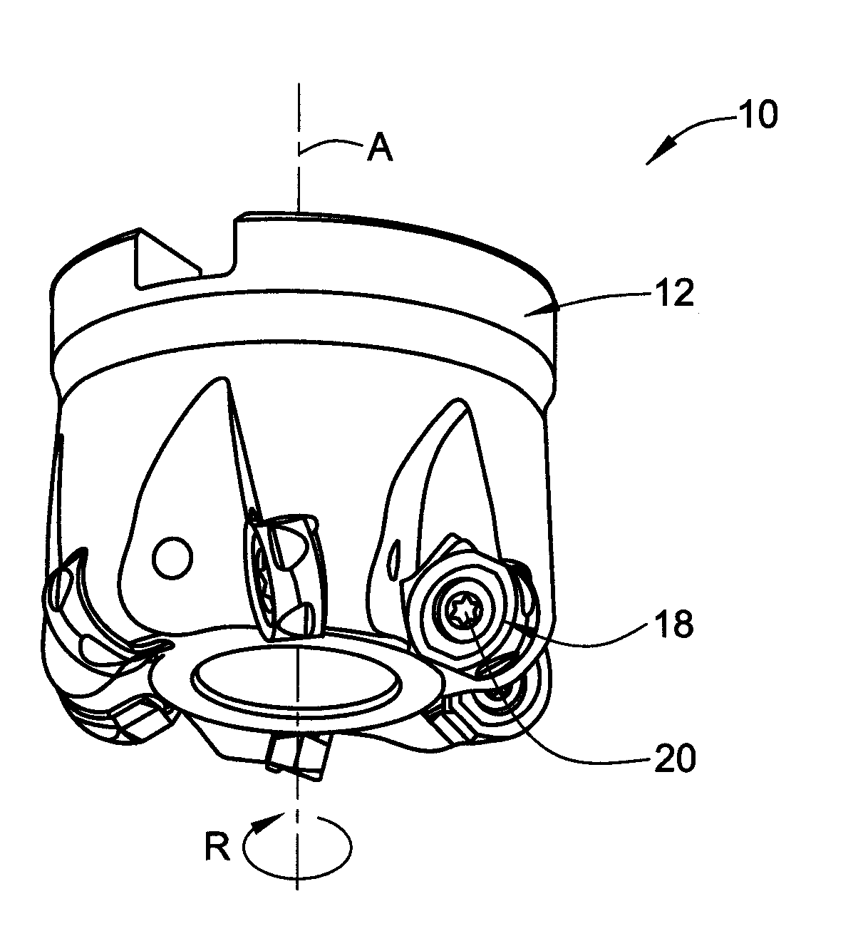
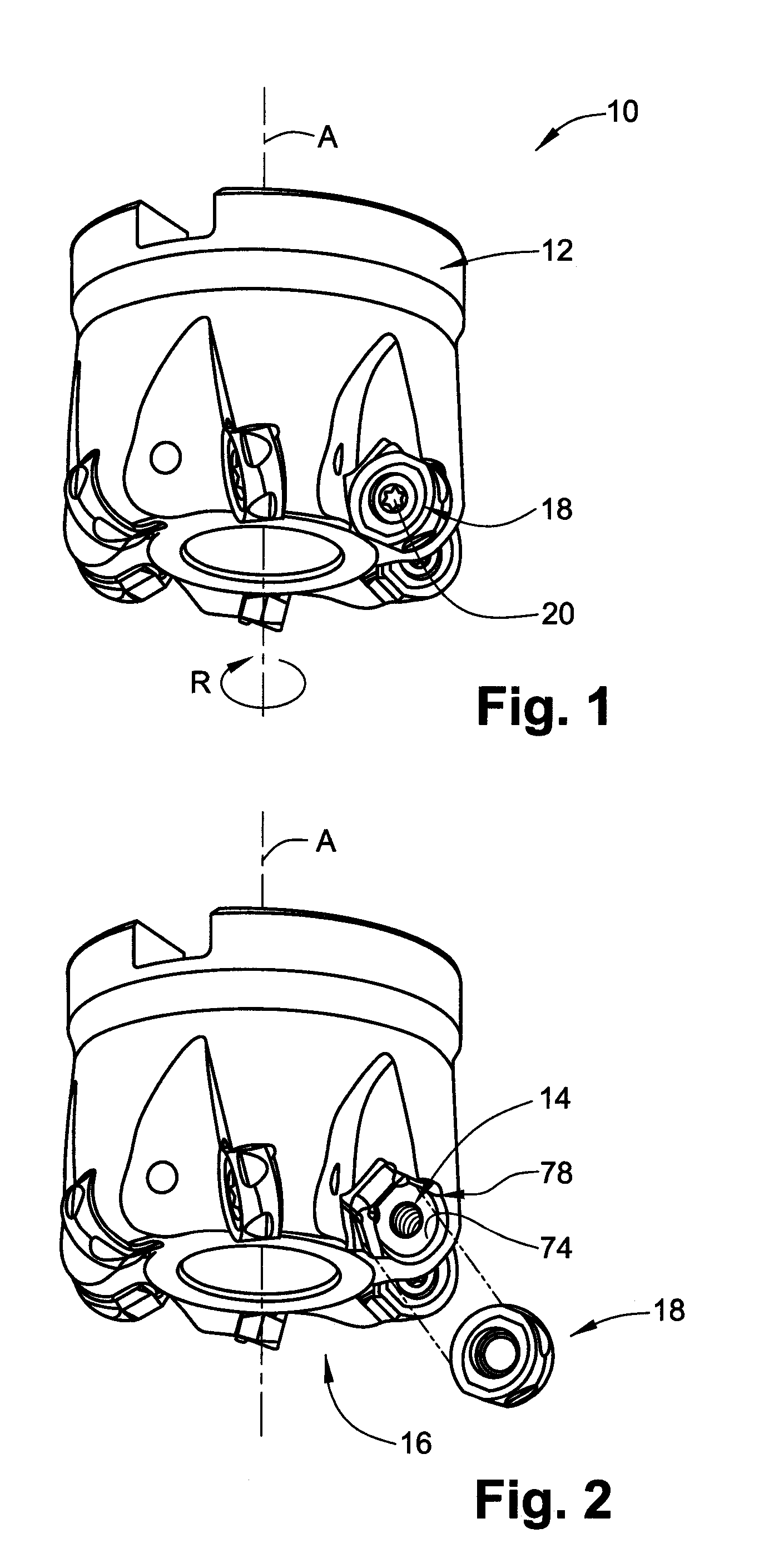
[0059]Attention is first drawn to FIGS. 1 and 2 showing a cutting tool 10 in accordance with the present invention. The cutting tool 10 has a longitudinal axis of rotation A defining a front-to-rear direction of the cutting tool 10 and a direction of rotation R. The cutting tool 10 comprises a tool body 12 having a plurality of insert pockets 14 formed in a front end 16 of the tool body 12. A cutting insert 18 is retained in each of the insert pockets 14 by means of a clamping screw 20. The cutting insert 18 may be preferably made from cemented carbide powders by pressing and sintering or by injection molding techniques.

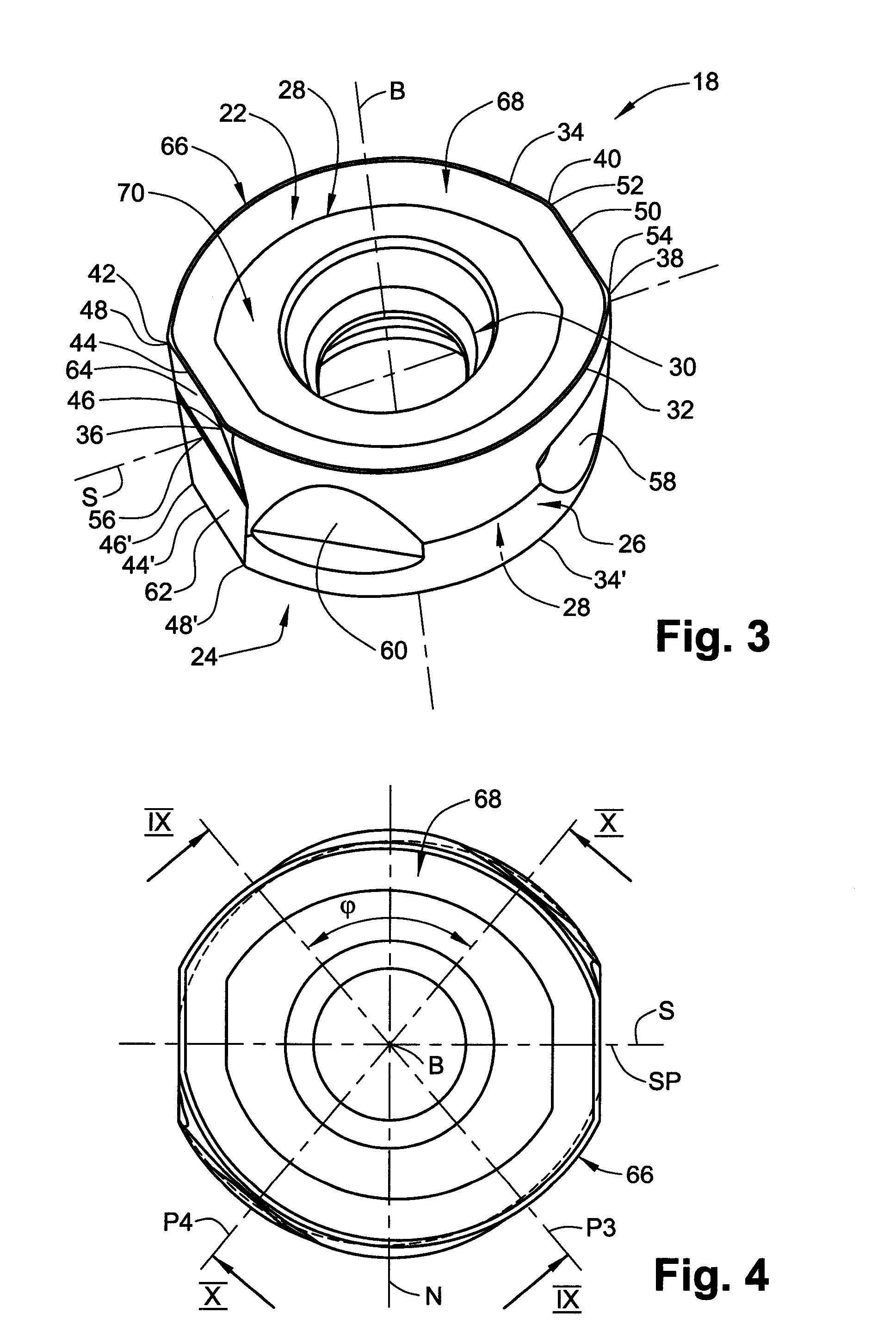
[0060]Attention is now drawn to FIGS. 3 to 10. The cutting insert 18 comprises an upper surface 22, defining a first reference plane P1, a lower surface 24, defining a second reference plane P2, and a peripheral surface 26 extending between the upper surface 22 and the lower surface 24. The upper surface 22 and the lower surface 24 constitute end surfaces 28 of the c...


PUM

PropertyMeasurementUnit
Angleaaaaaaaaaa
Angleaaaaaaaaaa
Angleaaaaaaaaaa

Abstract

A cutting insert for retention in a rotating cutting tool having an axis of rotation has two opposing end surfaces and a peripheral surface extending therebetween, each end surface having a mutual first axis of symmetry passing through the end surfaces about which each end surface has N-fold rotational symmetry for some value of N where N is chosen from the group consisting of 2, 3 and 4. A peripheral cutting edge is formed at the junction between each end surface and the peripheral surface, the peripheral cutting edge having N curved cutting edges merging with N straight cutting edges which extend between the curved cutting edges at extremities thereof. The curved cutting edges of the two end surfaces are not aligned in an end view of the cutting insert along the first axis of symmetry.

Description

FIELD OF THE INVENTION[0001]The present invention relates to a milling cutting insert having rounded cutting edges and particularly to a double-sided cutting insert of such a kind.BACKGROUND OF THE INVENTION[0002]When producing turbine blades, the final machining stage of the internal surface of the turbine blade is typically done by means of milling cutting inserts having round cutting edges. In such a case, the total usable sector used to cut by such a cutting insert is usually greater than 120°, therefore, the cutting insert may be indexed only two times since a third indexing would not be able to utilize a full range sector, i.e., a cutting edge spanning more than 120°.[0003]Known round cutting inserts or cutting inserts having round cutting edges are often single sided, and, as mentioned, may fully utilize only two cutting edges. For example, US. Pat. No. 4,175,896 discloses a single sided cutting insert having two arcuate cutting edges which are eccentric to each other and sep...

Claims


Application Information

Patent Timeline
IPC IPC(8): B26D1/12B26D1/00
CPCB23C5/202B23C5/2213B23C2200/128Y10T407/1924B23C2210/168B23C5/2221Y10T407/23B23C2200/203B23C5/20B23B27/16B23C2200/201
Inventor MEN, YURISATRAN, AMIR
Owner ISCAR LTD
Why Eureka
Try Eureka