
Turbomachine with unducted propellers

a turbomachine and propeller technology, applied in the direction of machines/engines, air-flow influencers, transportation and packaging, etc., can solve the problems of reducing the thrust produced by the downstream propeller, the noise generated by the turbomachine when operating, and the turbomachine must comply with relatively severe acoustical certification standards. , to achieve the effect of simple, effective and economical

Inactive Publication Date: 2010-03-04
SN DETUDE & DE CONSTR DE MOTEURS DAVIATION S N E C M A
View PDF7 Cites 13 Cited by
  • Summary
  • Abstract
  • Description
  • Claims
  • Application Information

AI Technical Summary

Benefits of technology

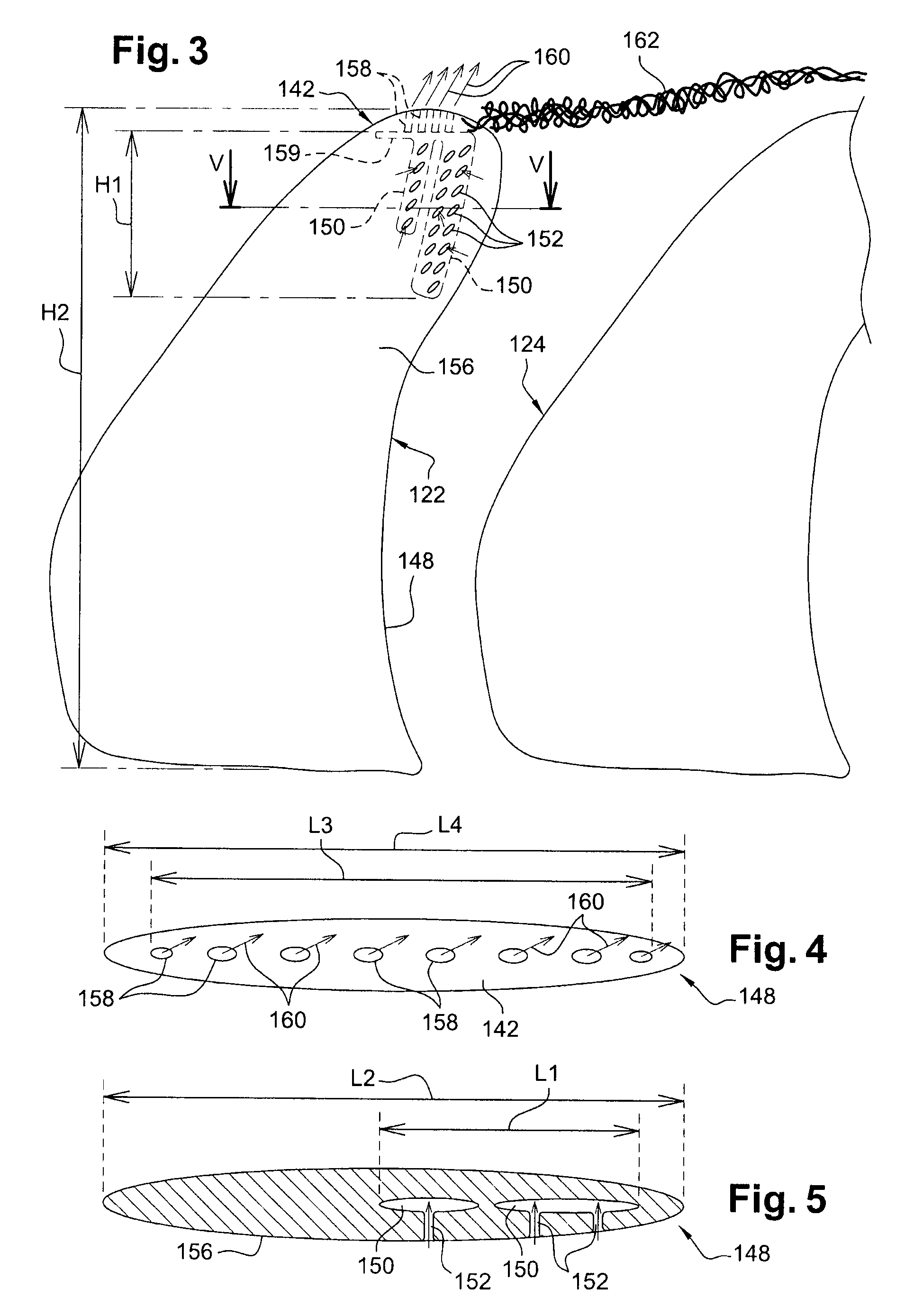
The invention proposes a solution to the problem of clipping caused by the interaction of vortices generated by the blades of a turbomachine. The solution involves the use of air tapping orifices on the blades to destroy the coherency of the vortices and reduce the clipping provoked by the interaction of these vortices with the blades of the downstream propeller. The air tapping orifices are located on the radially external end portions of the blades and are connected to the interior of the blades through substantial radial shafts. The air tapping orifices allow for the evacuation of air from the blades and the destruction of the vortices generated by the blades of the upstream propeller. The invention does not require any modification to the dimensions of the propellers and can be easily integrated into existing turbomachines.

Problems solved by technology

However, the major disadvantage with this type of turbomachine is the noise that it generates when operating.
Yet, this turbomachine must comply with relatively severe acoustical certification standards, in particular during the take-off and landing phases of the aircraft provided with this turbomachine.
One of the sources of this noise is caused by the interaction with the blades of the downstream propeller of a vortex or of vortices generated on heads of the blades of the upstream propeller, with the blades of the downstream propeller.
However, this solution is not entirely satisfactory as it results in a reduction of the thrust produced by the downstream propeller and as such a decrease in the performance of the turbomachine.
It would be possible to increase the load of the downstream propeller in order to compensate for the reduction in its diameter, but this propeller would then become more complex mechanically to carry out and it would generate its own louder clipping.

Method used


Image

  • Turbomachine with unducted propellers
  • Turbomachine with unducted propellers
  • Turbomachine with unducted propellers

Examples


Embodiment Construction

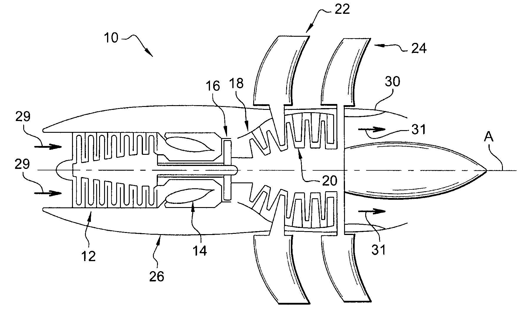
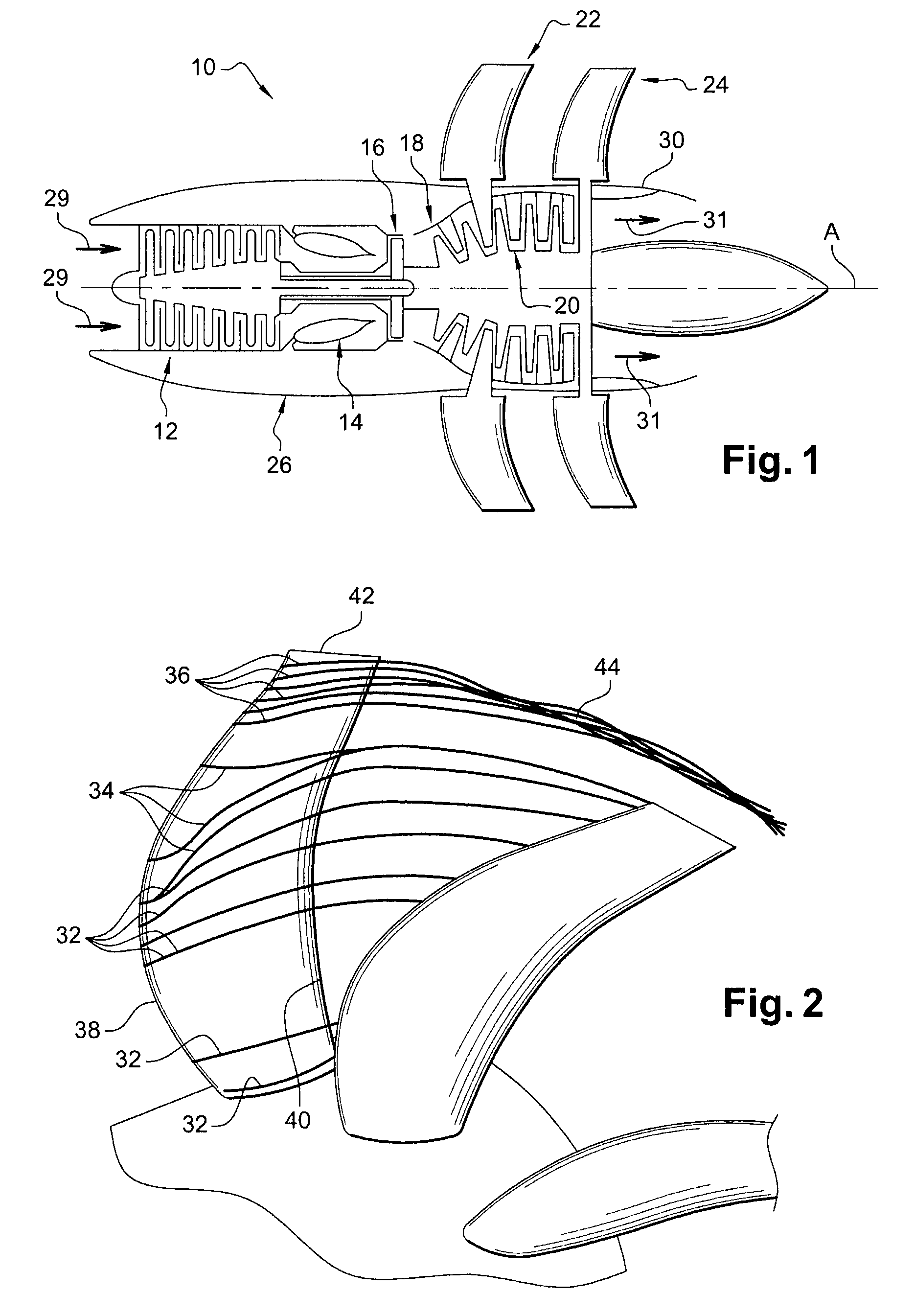
[0025]Reference is first made to FIG. 1 which shows a turbomachine 10 with unducted propellers which comprises from upstream to downstream, in the flow direction of gases inside the turbomachine, a compressor 12, an annular combustion chamber 14, a high-pressure upstream turbine 16, and two low-pressure downstream turbines 18, 20 which are contra-rotating, i.e. they rotate in opposite directions around the longitudinal axis A of the turbomachine.

[0026]Each one of these downstream turbines 18, 20 is secured in rotation to an external propeller 22, 24 which extends radially to the exterior of the nacelle 26 of the turbomachine, with this nacelle 26 being substantially cylindrical and extending along the axis A around the compressor 12, the combustion chamber14, and the turbines 16, 18 and 20.

[0027]The flow of air 29 that penetrates into the compressor 12 is compressed and is then mixed with fuel and burned in the combustion chamber 14, the combustion gases being then injected into the...


PUM


Abstract

Turbomachine, comprising two external coaxial and contra-rotating unducted propellers (122, 124), at least some of the blades (148) of the upstream propeller comprising substantially radial internal shafts for air circulation (150) communicating with air tapping orifices (152) in the boundary limits of the blades, and at their radially external ends with air outlet orifices (158).

Description

[0001]This invention relates to a turbomachine of the unducted propeller type.BACKGROUND OF THE INVENTION[0002]A turbomachine of this type comprises two contra-rotating and coaxial external propellers, respectively upstream and downstream, which are each secured in rotation to a turbine of the turbomachine and which extend substantially radially to the exterior of the nacelle of this turbomachine. This turbomachine has the advantage of being of high performance compared to other types of turbomachine because it consumes less fuel and because its contra-rotating propellers make it possible to provide a relative substantial thrust.[0003]However, the major disadvantage with this type of turbomachine is the noise that it generates when operating. Yet, this turbomachine must comply with relatively severe acoustical certification standards, in particular during the take-off and landing phases of the aircraft provided with this turbomachine.[0004]One of the sources of this noise is caused ...

Claims


Application Information

Patent Timeline
Patent Type & Authority Applications(United States)
IPC IPC(8): F01D1/24F01D5/14
CPCB64C11/18B64C11/48Y02T50/66Y02T50/166B64C21/04Y02T50/10Y02T50/60
Inventor MOREL, CEDRIC
Owner SN DETUDE & DE CONSTR DE MOTEURS DAVIATION S N E C M A
Learn More