Blade

Active Publication Date: 2010-03-04
ROLLS ROYCE PLC
View PDF43 Cites 19 Cited by
  • Summary
  • Abstract
  • Description
  • Claims
  • Application Information

AI Technical Summary

Benefits of technology

[0009]The root part may have a length, and the zone of weakness may be arranged to reduce the ability of the root part to withstand a force applied transversely across the length of the root

Problems solved by technology

The root part may be curved in the form of an arc, and the zone of weakness may reduce the ab

Method used


Image

  • Blade
  • Blade
  • Blade

Examples


Embodiment Construction

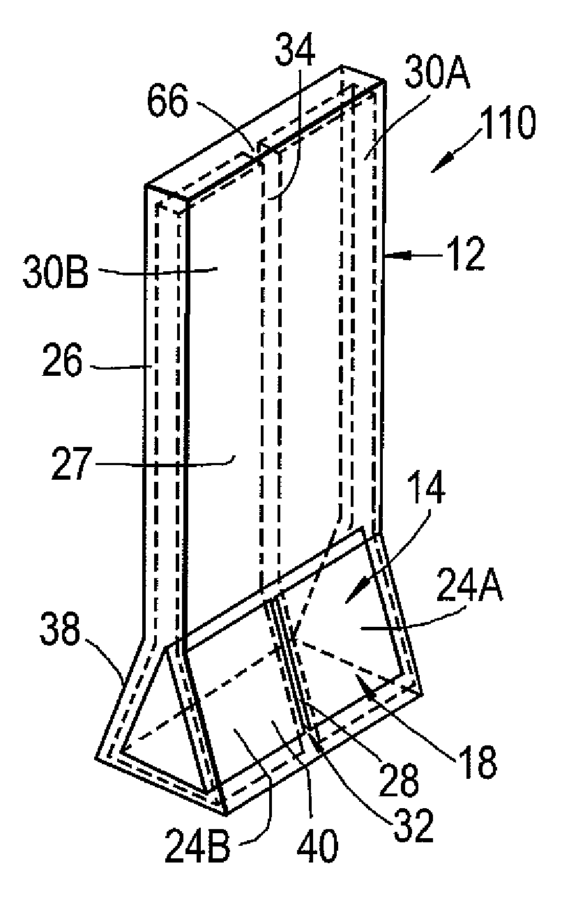
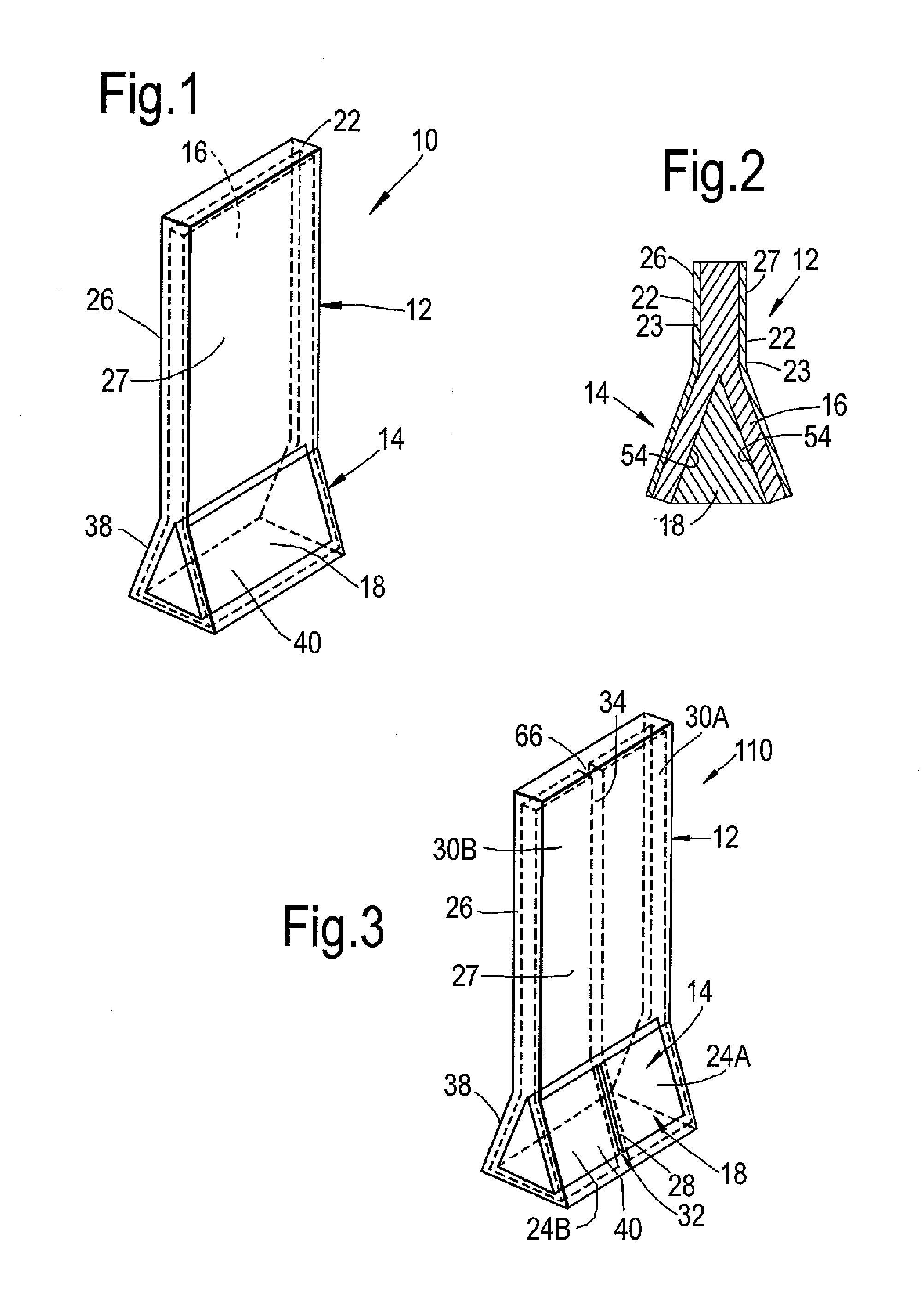
[0031]Referring to FIGS. 1 and 2, a known blade 10 includes an aerofoil part 12 and a root part 14, the aerofoil part 12 extending from the root part 14. The blade 10 includes a structural part 16 and a root former 18. The root former 18 is in the form of a wedge or prism, having a length, which extends transversely across the blade 10 and having a substantially triangular shape in cross section. The structure 16 in the example shown in FIG. 1 extends substantially throughout the aerofoil part 12 and along side walls 54 of the root former 18, so that the root former 18 is received within the structure 16. The blade 10 includes a settable material 22, which surrounds the structure 16 and the root former 18, and forms a surface layer 23. The root former 18 serves to splay the structure 16 to form the root part 14. The settable material 22 may be made from several layers, which impart properties of colour, erosion protection, surface finish, and the like.

[0032]In one example, the struc...


PUM

PropertyMeasurementUnit
Lengthaaaaaaaaaa
Forceaaaaaaaaaa

Abstract

A fan blade for a gas turbine engine has an aerofoil part and a root part. The root part includes a root former; the root former 18 includes a zone of weakness, which reduces the ability of the root part to withstand an impact force. Thus, in an impact situation in which the fan blade has separated from the fan rotor and the fan blade has itself separated into fragments, the root part will fracture or buckle more easily than would be the case with conventional arrangements. This will lower the impact force of the root part upon the fan casing, thus permitting the fan casing to be designed to withstand lower impact forces. The fan casing can therefore be made lighter, and cheaper, than in conventional arrangements.

Description

CROSS REFERENCE TO RELATED APPLICATION[0001]This application is entitled to the benefit of British Patent Application No. GB 0815475.9, filed on Aug. 27, 2008.FIELD OF THE INVENTION[0002]The present invention relates to a blade, particularly but not exclusively a blade for a gas turbine engine.BACKGROUND OF THE INVENTION[0003]A turbofan gas turbine engine comprises a fan, which comprises a fan rotor and a number of circumferentially spaced radially outwardly extending fan blades secured to the fan rotor. The fan is surrounded by a fan casing, which defines a fan duct. The fan casing is arranged to contain one or more of the fan blades in the unlikely event that a fan blade becomes detached from the fan rotor. Safety regulations dictate that the worst case of this scenario—in which the whole blade is released—must be provided for in the design of the fan casing.[0004]If a fan blade becomes detached from the fan rotor, the released fan blade will strike a main fan casing containment r...

Claims


Application Information

Patent Timeline
IPC IPC(8): F01D5/14
CPCF01D5/14F05D2300/612F01D21/045F01D5/147
Inventor BECKFORD, PETER ROWLANDREAD, SIMONDEUCHAR CARE, IAN COLIN
Owner ROLLS ROYCE PLC
Why Eureka
Try Eureka