Back plug-in connector device

a plug-in and connector technology, applied in the direction of coupling device connection, coupling base/case, incorrect coupling prevention, etc., can solve the problems of high cost, complex structure, and only the required number of terminal pins at the largest, and achieve low cost, simple structure, and high productivity.

Inactive Publication Date: 2010-03-04
NEC CORP +1
View PDF15 Cites 4 Cited by
  • Summary
  • Abstract
  • Description
  • Claims
  • Application Information

AI Technical Summary

Benefits of technology

[0015]It is an object of the present invention to provide a back plug-in connector device which is easy to fabricate due to a simple structure, enables a smooth three-dimensional floating, reduces maintenance such as replacement caused by connector damage and reduces fabrication cost.
[0017]A first effect of the present invention is that a three-dimensional floating can be realized and a high productivity can be obtained at a low cost. The reason is that the structure is simpler than conventional connectors, an assembling from one direction becomes possible and a number of screws can be reduced.
[0018]A second effect of the present invention is that smoother floating is realized compared to conventional connectors. The reason is that a friction coefficient during the three-dimensional floating between a groove portion of the body chassis and a projection portion of the floating support plate can be reduced.
[0019]A third effect of the present invention is that frequency of maintenance such as a replacement of the connector caused by a connector breakage can be reduced.Preferred Modes

Problems solved by technology

A first problem of the structure of the conventional back plug-in connector shown in FIG. 6 is that a required number of terminal pins is only about 24 at largest.
A second problem of the commercial back plug-in connector is that the structure becomes complicated and thus high cost because floating bushes and guide pins etc. are provided.
The structure disclosed in Patent Document 1 has a problem of high cost because a complicated engaging latch is provided on the connector and the correspondent engaging hole is necessary on the plate.
A first problem of the structure disclosed in Patent Document 2 is that there is a possibility of breakage of the connector after repeated plug in and out caused by an engaging gap due to a plastic deformation of the elastic support strip.
A second problem is that various kinds of designs of the elastic support strips are needed corresponding to design differences of the connectors such as a number of pins, etc. to prevent plastic deformation of the support strip.
The structure is not simple enough and a floating in a plug-in direction is not capable.

Method used


Image

  • Back plug-in connector device
  • Back plug-in connector device
  • Back plug-in connector device

Examples


Embodiment Construction

s

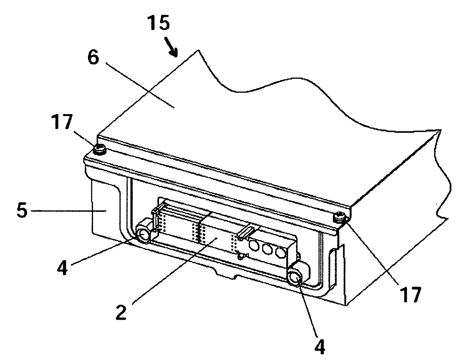
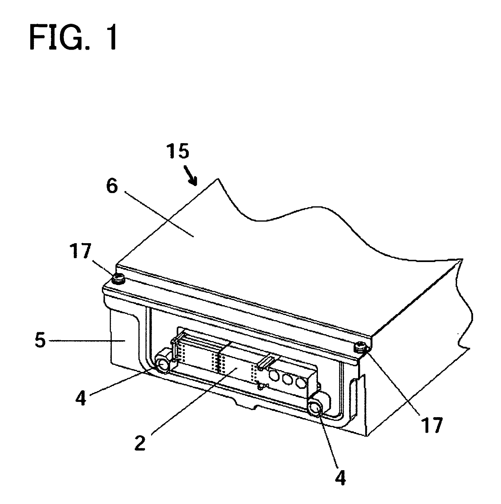
[0020]Exemplary embodiments of the present invention are as follows. In a second aspect of the present invention, a projection portion is provided on an edge surface portion of the support plate and a groove portion which engages the projection portion with a necessary clearance is provided on the body chassis.

[0021]In a third aspect of the present invention, the floating structure is constituted such that the support plate having the projection portion is fitted into the body chassis having the groove portion and that the cover is fixed to the body chassis from the same direction so as to sandwich the support plate.

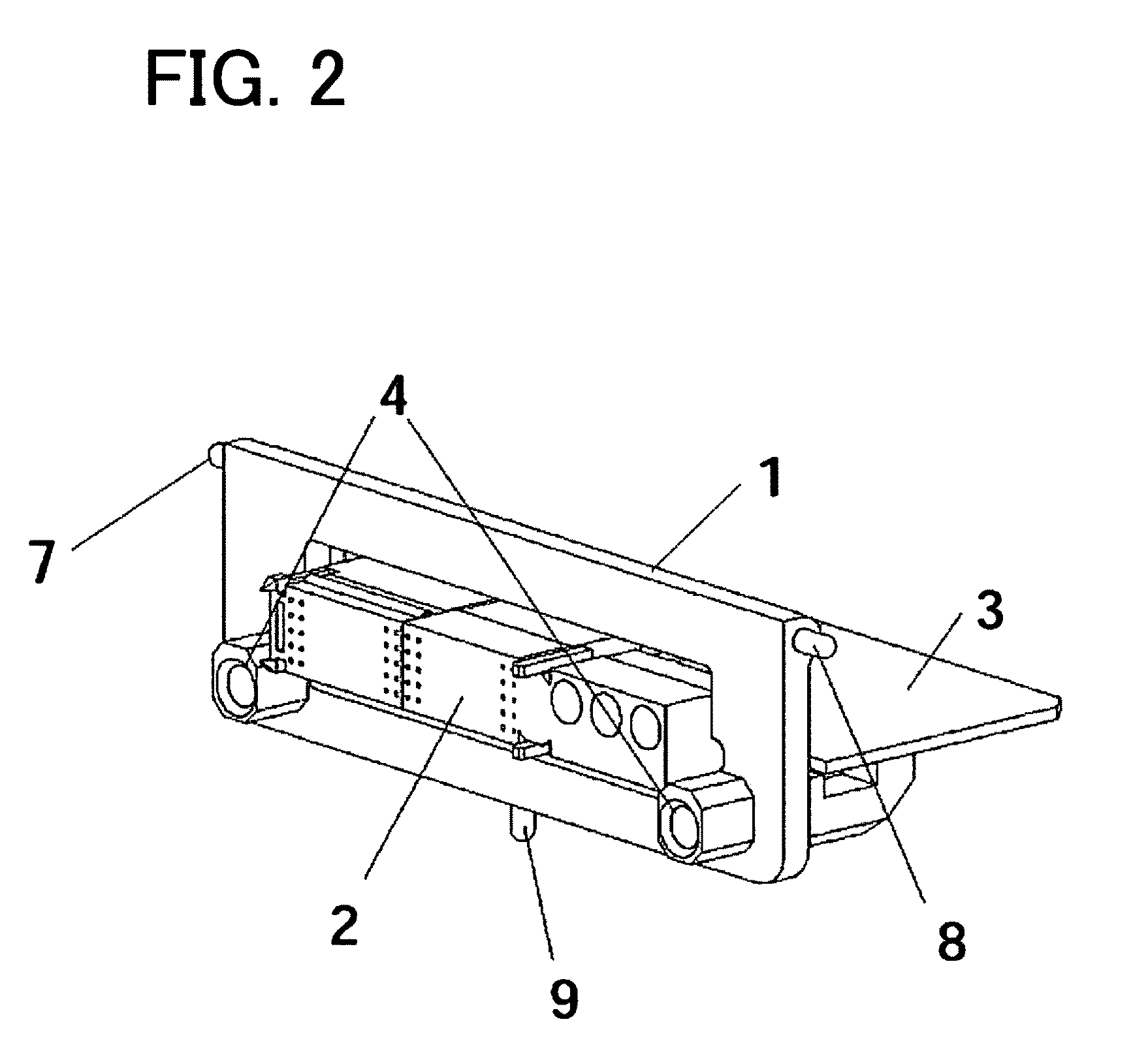
[0022]In a fourth aspect of the present invention, the projection portion is cylinder-shaped.

[0023]In a fifth aspect of the present invention, an end portion of the cylinder-shaped projection portion is sphere-shaped or semi-sphere-shaped.

[0024]In a sixth aspect of the present invention, at least one projection portion which engages the groove portion is provided on eac...


PUM


Abstract

A back plug-in connector device having a floating structure, comprises: a body chassis, a cover and a support plate on which a connector is mounted. The support plate is sandwiched by the body chassis and the cover so as to constitute the floating structure.

Description

REFERENCE TO RELATED APPLICATION[0001]This application is the National Phase of PCT / JP2008 / 056706, filed Apr. 3, 2008, which claims the benefit of the priority of Japanese patent application No. 2007-098338, filed on Apr. 4, 2007, the disclosures of which are incorporated herein in their entirety by reference thereto.TECHNICAL FIELD[0002]This invention relates to a back plug-in connector device, and particularly relates to a back plug-in connector device having a floating structure.BACKGROUND ART[0003]Various kinds of connector devices each having a floating structure have been disclosed. For example, a structure of a conventional commercial back plug-in connector is shown in FIG. 6. The connector comprises a connector (backboard side) 21 having a guide projection for positioning and a connector part 22 having a guide hole, and a fixation screw hole of the connector part is floating.[0004]Patent Document 1 discloses a connector having an engaging latch on a connector and an engaging...

Claims


Application Information

Patent Timeline
Patent Type & Authority Applications(United States)
IPC IPC(8): H01R13/46
CPCH05K7/1454H01R13/6315
Inventor MATSUZAWA, TADASHIKADOMATSU, KEIJIROU
Owner NEC CORP
Why Eureka
Try Eureka