Electrical connectors

a technology of electrical connectors and connectors, applied in the direction of electrical apparatus, electrical discharge lamps, coupling device connections, etc., can solve the problems of imposing considerable constraints on the physical ability of assemblers, exacerbate problems, and miniature connectors such as micro-miniaturized d-type connectors, and achieve the effect of enduring electrical breakage better

Inactive Publication Date: 2010-03-04
CINCH CONNECTORS
View PDF7 Cites 5 Cited by
  • Summary
  • Abstract
  • Description
  • Claims
  • Application Information

AI Technical Summary

Benefits of technology

[0014]The contacts of the present invention are held together against axial forces resulting from the resilience of the flexible conductive structures held in place by a known locking mechanism, or retained by epoxy. This causes the plug and socket elements to self-eject when released. Since solid pins are capable of being used, such a connector arrangement according in the present invention can carry more current than most nanominiature con

Problems solved by technology

There is often a requirement that the connectors should be as small as possible and this has put considerable constraints on the ability of assemblers to physically make connection between connector pins and sockets and between the wires of a cable and the pins or sockets of a connector part.
The problems are exacerbated if the connector has to be suitable for use in a hostile environment where it may be subjected to substantial amounts of vibration, or if it has to carry a large amount of current in relation to the pitch and physical size of the contacts.
Miniature connectors such as micro-miniature D-ty

Method used


Image

  • Electrical connectors
  • Electrical connectors
  • Electrical connectors

Examples


Embodiment Construction

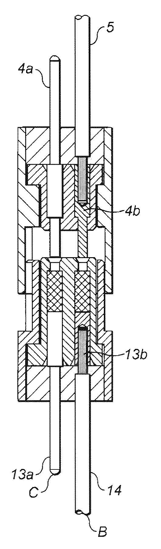
[0022]An aspect of the nanominiature connector arrangement of the present invention is shown in FIGS. 5a and 5b. The advantage of this arrangement is that higher current flows can be achieved since it is possible to use basic solid turned contacts, which are crimped or soldered to wires, without requiring any modification in the pins or the sockets for providing the additional grip. This is achieved by including a flexible conductive structure interposed between these contact faces. This flexible structure of the present invention is formed of highly conductive material i.e. having highly conductive wires or other conductive means.

[0023]This structure acts as a z-axis compression interconnect between the plug and socket connectors. The Z-axis compression interconnect device provides a force in the direction of the longitudinal axis (i.e. the z-axis direction) of the pins of the plug and the socket contacts when these are held in a mated state. This z-axis compressibility in intercon...


PUM


Abstract

The invention relates to a miniature electrical connector arrangement, and particularly to a socket connector for use in such a miniature connector arrangement. The socket connector comprises an outer connector body for enclosing one or more cavities. Each cavity is provided with one or more electrical contacts that can be connected to a length of one or more conductive elements. One or more flexible conductive structures are placed within the cavities and proximate to the contacts of the socket connector are capable of z-axis compressibility. The flexible conductive structures are arranged to connect to one or more pins of a plug connector of the miniature connector arrangement when the plug and socket connectors are attached with each other for conducting current.

Description

FIELD OF THE INVENTION[0001]The present invention relates to electrical connectors and more particularly to miniature connectors and a method of connection for such connectors.BACKGROUND OF THE INVENTION[0002]Many pieces of modern electrical equipment are now connected together using multi-way connectors in view of the need to couple a considerable number of wires, where each may be required for a particular application. Various standard systems have been utilized in the past, such as D-type connectors that are known to be used for serial connections to computers. Common D-type connectors have two rows of pins spaced approximately 0.108 inch (2.74 mm) apart, with the rows spaced 0.112 inches apart (2.84 mm). 9, 15, 25 and 37-way connectors are known.[0003]There is often a requirement that the connectors should be as small as possible and this has put considerable constraints on the ability of assemblers to physically make connection between connector pins and sockets and between the...

Claims


Application Information

Patent Timeline
IPC IPC(8): H01R24/00
CPCH01R13/187
Inventor MADELEY, JOHN NIGEL
Owner CINCH CONNECTORS
Why Eureka
Try Eureka