Low power radio frequency receiver

a radio frequency receiver, low-power technology, applied in the field of radio frequency receivers, can solve the problems of limited operating time of conventional portable receivers, limited power supply, and relatively fast battery exhaustion, and achieve the effect of saving available power supply resources

Inactive Publication Date: 2010-03-04
AUDIODENT ISRAEL
View PDF17 Cites 13 Cited by
  • Summary
  • Abstract
  • Description
  • Claims
  • Application Information

AI Technical Summary

Benefits of technology

[0014]The present invention relates to a method and system for providing a low power radio frequency recei...

Problems solved by technology

One of the main constraints of a conventional portable communication system is a constraint of the power supply due to limited power resources (such as a battery, an accumulator, etc.).
However, conventional portable receivers usually require significant power recourses, leading to the relatively fast battery exhaustment.
Thus, the operating time of conventional portable receivers is limited due to the power supply constraints.
However, this current consumption is still relatively large to use said RF receiver with portable power supply resources (e.g....

Method used


Image

  • Low power radio frequency receiver
  • Low power radio frequency receiver
  • Low power radio frequency receiver

Examples


Embodiment Construction

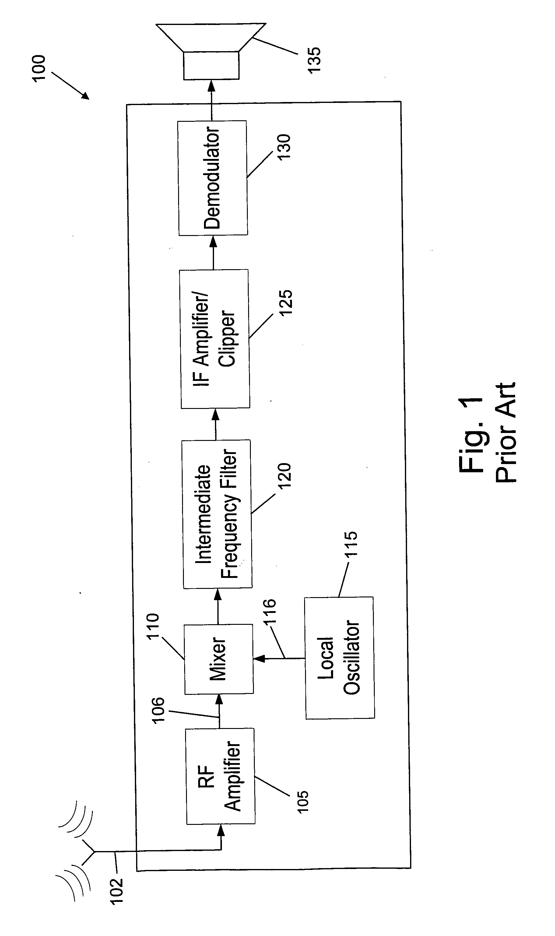
[0044]FIG. 1 is a schematic block diagram of a conventional FM receiver 100, according to the prior art. The receiver comprises: an RF (Radio-Frequency) amplifier 105 for amplifying the radio signal received by means of antenna 102; a Local Oscillator 115 for generating a signal with a predefined radio frequency to be mixed with the signal received by said antenna 102 to a different radio frequency; a Mixer 110 for mixing the signal received by said antenna 102 with the signal generated by said Local Oscillator 115; Intermediate Frequency (IF) filter 120 (Band-pass filter) for passing signals between the filter low and high cutoff frequencies, but attenuating other signals in frequencies lower or higher than its predefined cutoff frequencies; an IF amplifier / clipper 125 for amplifying the intermediate frequency signal received from said Intermediate Frequency filter 120; and a Demodulator 130 for demodulating the corresponding data contents (such as audio data, etc.) from the signal...


PUM


Abstract

The invention relates to a low power radio frequency receiver which comprises: (a) an antenna for receiving a first radio frequency signal; (b) a radio frequency amplifier for amplifying the first radio frequency signal received by said antenna; (c) an oscillator for generating a second radio frequency signal having a predefined frequency and a predefined duty cycle to be mixed with said first radio frequency signal received by said antenna; (d) a mixer for mixing the first amplified radio frequency signal with second radio frequency signals and generating a third radio frequency signal; (e) an intermediate frequency filter for passing one or more intermediate frequencies of said third radio frequency signal and attenuating other frequencies of said third signal that are lower or higher than its cutoff frequencies, characterized in that it further comprises: (f) one or more switches for periodically and synchronously switching ON and OFF one or more of said radio frequency amplifier, said oscillator, and said mixer, said switches controlled by means of a control signal having a frequency that is higher than the frequency of data embedded within said first radio frequency signal; and (g) a control unit located within said radio frequency receiver for providing said control signal, wherein each of said switches is connected to a corresponding capacitor within said radio frequency amplifier, or oscillator, or mixer, said capacitor storing an operating point of said radio frequency amplifier, or oscillator, or mixer when said radio frequency amplifier, or oscillator, or mixer is switched OFF.

Description

FIELD OF THE INVENTION[0001]The present invention relates to radio frequency receivers. More particularly, the invention relates to a method and system for providing a low power radio frequency receiver (such as an FM or AM receiver) that significantly saves available power supply resources, such as a battery.DEFINITIONS, ACRONYMS AND ABBREVIATIONS[0002]Throughout this specification, the following definitions are employed:Frequency Modulation (FM): is a form of modulation which represents information as variations in the instantaneous frequency of a carrier wave (contrast to Amplitude Modulation (AM), in which the amplitude of the carrier is varied while its frequency remains constant).IF (Intermediate Frequency) Amplifier: is a device for converting a small intermediate frequency input signal into a larger intermediate frequency output signal.Intermediate Frequency Filter: is a Band-pass filter that passes intermediate frequencies well, but attenuates (or reduces) other frequencies...

Claims


Application Information

Patent Timeline
IPC IPC(8): H04B1/16
CPCH04W52/028Y02D30/70
Inventor LIEBMAN, VADIM
Owner AUDIODENT ISRAEL
Why Eureka
Try Eureka