Refrigerant system with economizer, intercooler and multi-stage compressor

a refrigeration system and compressor technology, applied in the direction of gas cycle refrigeration machines, compression machines with cascade operation, refrigeration machines, etc., can solve the problems of less practicability of intercooler provision, exceeding safety or reliability limits, and extremely high refrigerant discharge temperature, etc., to improve the performance of the refrigerant system, the effect of enhancing heat rejection capability and increasing temperature differential

Inactive Publication Date: 2010-03-11
CARRIER CORP
View PDF11 Cites 24 Cited by
  • Summary
  • Abstract
  • Description
  • Claims
  • Application Information

AI Technical Summary

Benefits of technology

[0010]Preferably, the intercooler heat exchanger is positioned between the higher compression stages of the multi-stage compression system (with more than two compression stages), where refrigerant temperatures have reached higher values, allowing for larger temperature differentials between the refrigerant and a secondary fluid, enhancing heat rejection capability, and improving performance of the refrigerant system. This is especially beneficial when ambient air is utilized directly or indirectly (e.g., through auxiliary loops with an intermediate fluid, such as city water) as a secondary fluid, in particular, at high ambient temperatures. The locations for the intercooler and the economizer circuit can be interchanged, with the intercooler positioned between the lower compression stages and the economizer circuit positioned between the higher compression stages, depending on the temperature of the secondary fluid utilized in the intercooler and capacity vs. efficiency tradeoff for the economizer circuit.
[0011]On the other hand, strategically positioning the economizer circuit between the lower compression stages allows for larger temperature differentials in the economizer heat exchanger and thus for higher refrigerant cooling potential in the evaporator and the refrigerant system performance (capacity and / or efficiency) enhancement. Also, the colder refrigerant injected between the compression stages further reduces discharge temperature, improves reliability of the entire compression system, extends an operational envelope for the refrigerant system and enhances evaporator dehumidification capability. Lastly, positioning the economizer circuit between lower compression stages allows for a larger step in refrigerant system unloading strategy, which is desired in most of the applications.
[0012]This is especially important in case of transcritical operation, where the high side temperature and pressure are independent from each other. In the transcritical operation, the discharge pressure is not limited by the discharge temperature anymore and can be adjusted to the value providing an optimum performance level. Thus, in such circumstances, the refrigerant system efficiency and capacity can be enhanced even further by optimizing the discharge pressure.

Problems solved by technology

If the compression ratio for the compressor system is high (which is typically the case for multi-stage compression systems) and / or refrigerant suction temperature is high (which is often the case for a refrigerant system equipped with a liquid-suction heat exchanger), then refrigerant discharge temperature can also become extremely high, and may exceed the limit defined by safety or reliability considerations.
However, the additional cost and complexity of the circuitry and components associated with the intercooler and economizer, makes the provision of the intercooler less feasible.

Method used


Image

  • Refrigerant system with economizer, intercooler and multi-stage compressor
  • Refrigerant system with economizer, intercooler and multi-stage compressor

Examples


Embodiment Construction

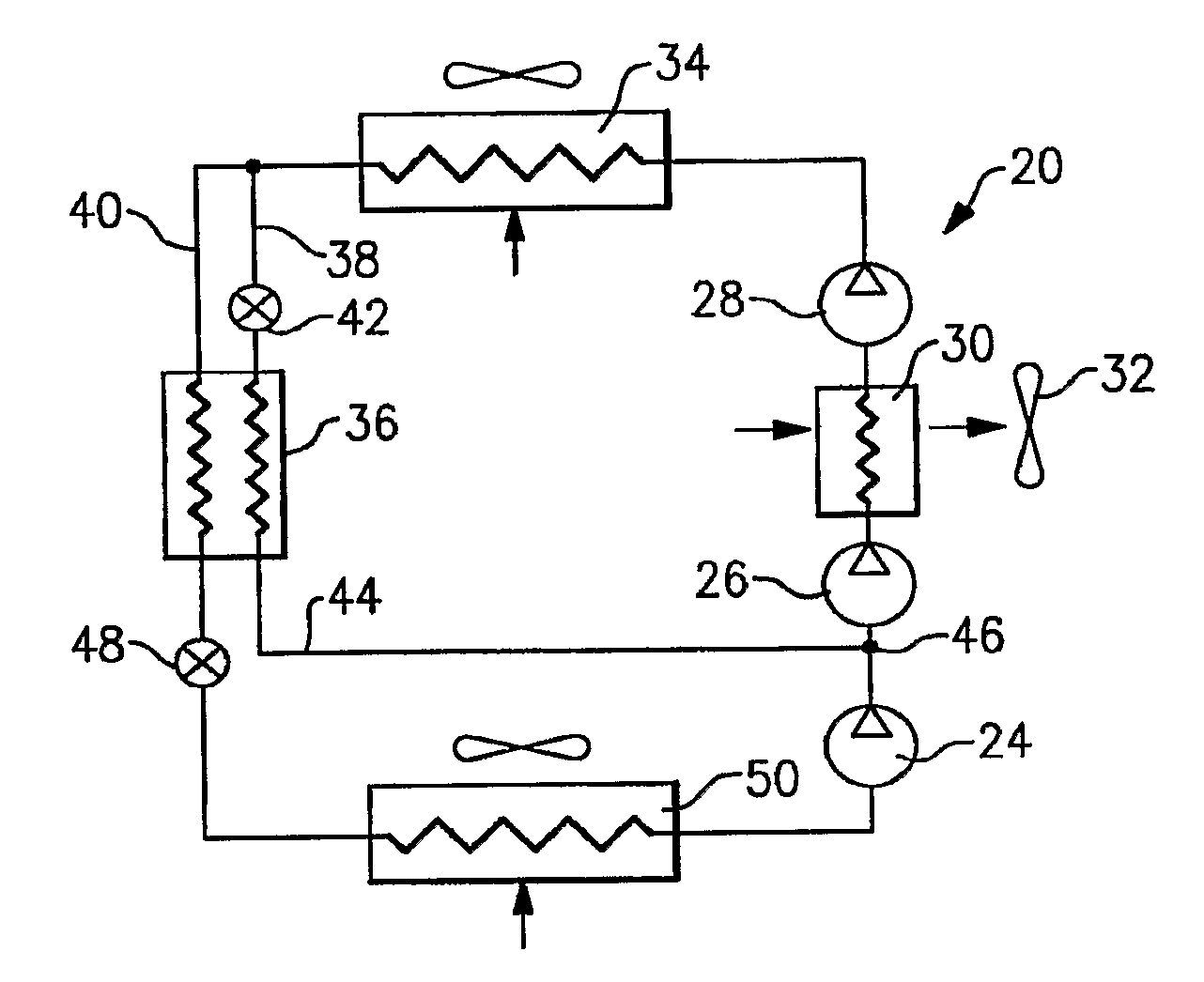
[0017]A refrigerant system 20 is illustrated in FIG. 1. Three stages of compression 24, 26, and 28 are positioned in series within the refrigerant system 20 to progressively compress refrigerant from suction to discharge pressure. Although a multi-stage compressor system is represented by separate compressor units that are disposed in series, as shown in FIG. 1, separate compression members can be utilized instead of some or all of the compressor units. Specifically, for instance, in the case of a three-stage reciprocating compressor, the three separate compression members may represent different banks of cylinders connected in series. Refrigerant, compressed by the first stage from a suction pressure to a first intermediate pressure, is delivered from a discharge outlet of this first stage to the suction inlet of the second stage. Refrigerant vapor is compressed by the second stage to a second intermediate pressure and delivered from a discharge outlet of this second stage to the s...


PUM


Abstract

A refrigerant system is provided with a multi-stage compression system. An intercooler is positioned between at least two compression stages to cool a refrigerant, by heat transfer interaction with a secondary fluid, after it has been compressed in the lower compression stages to some intermediate pressure. The intercooler enhances refrigerant system performance, improves compressor reliability, and extends operational envelope. Further, at least one economizer circuit is incorporated into the refrigerant system that returns the economized refrigerant flow at the location between at least two compression stages.

Description

BACKGROUND OF THE INVENTION[0001]This application relates to a refrigerant system with a multi-stage compressor that combines the benefits of an intercooler heat exchanger and an economizer cycle. In particular, this application relates to a refrigerant system operating, at least for a portion of the time, in a transcritical cycle.[0002]Refrigerant systems are known, and are utilized to condition a secondary fluid. As an example, an air conditioning system cools and dehumidifies air being delivered into a climate controlled environment.[0003]A basic refrigerant system includes a compressor compressing refrigerant and delivering that refrigerant through a discharge line downstream to a first heat exchanger, a so-called condenser for subcritical applications or a gas cooler for transcritical applications. In the first heat exchanger, the heat is removed from the refrigerant by a secondary media, such as ambient air. From the first heat exchanger, refrigerant passes through an expansio...

Claims


Application Information

Patent Timeline
Patent Type & Authority Applications(United States)
IPC IPC(8): F25B7/00F25B1/10F25B41/00
CPCF25B1/10F25B2400/072F25B2400/13F25B2309/06
Inventor LIFSON, ALEXANDERTARAS, MICHAEL F.
Owner CARRIER CORP
Why Eureka
Try Eureka