Method and apparatus for adjusting variable valve lift

Inactive Publication Date: 2010-03-11
DELPHI TECH INC
View PDF2 Cites 40 Cited by
  • Summary
  • Abstract
  • Description
  • Claims
  • Application Information

AI Technical Summary

Benefits of technology

[0007]Briefly described, an apparatus for adjusting individual valve lift in accordance with the present invention comprises a control arm assembly disposed between the cam lobes and the valve rockers for a multi-valve train. The control arm at each valve includes a driven gear. An actuator shaft driven by a motor as in the prior art includes a mating drive gear at each driven gear for rotating each control arm in a predetermined fashion to vary the overall lift of the valves. In the prior art, the mating driv

Problems solved by technology

Such low variation in air flow requi

Method used


Image

  • Method and apparatus for adjusting variable valve lift
  • Method and apparatus for adjusting variable valve lift
  • Method and apparatus for adjusting variable valve lift

Examples


Embodiment Construction

[0015]The present invention provides a method and apparatus for adjusting cylinder-to-cylinder air flow of a CVVL system during engine assembly and calibration to produce smooth idle quality by compensating for normal build tolerances.

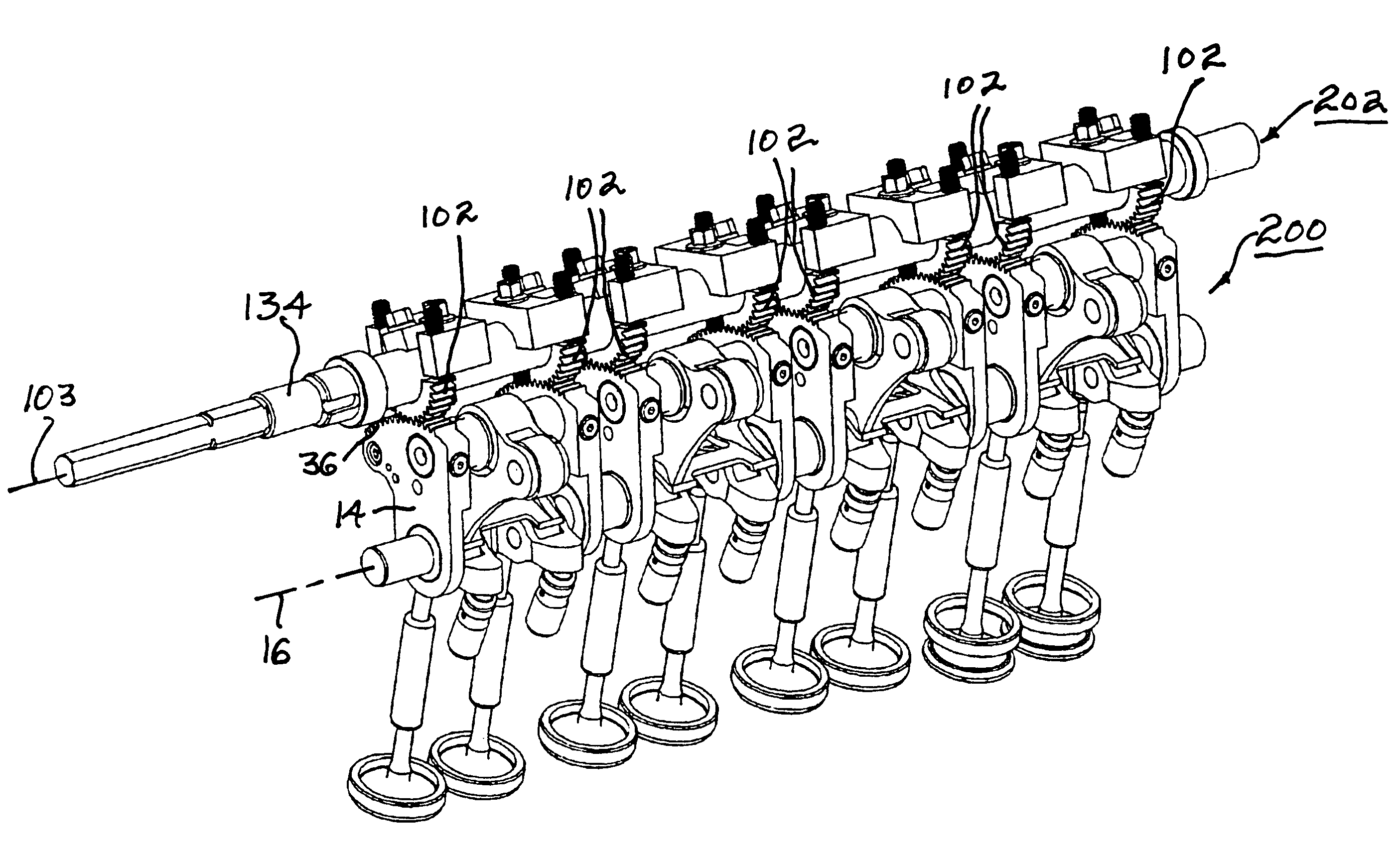
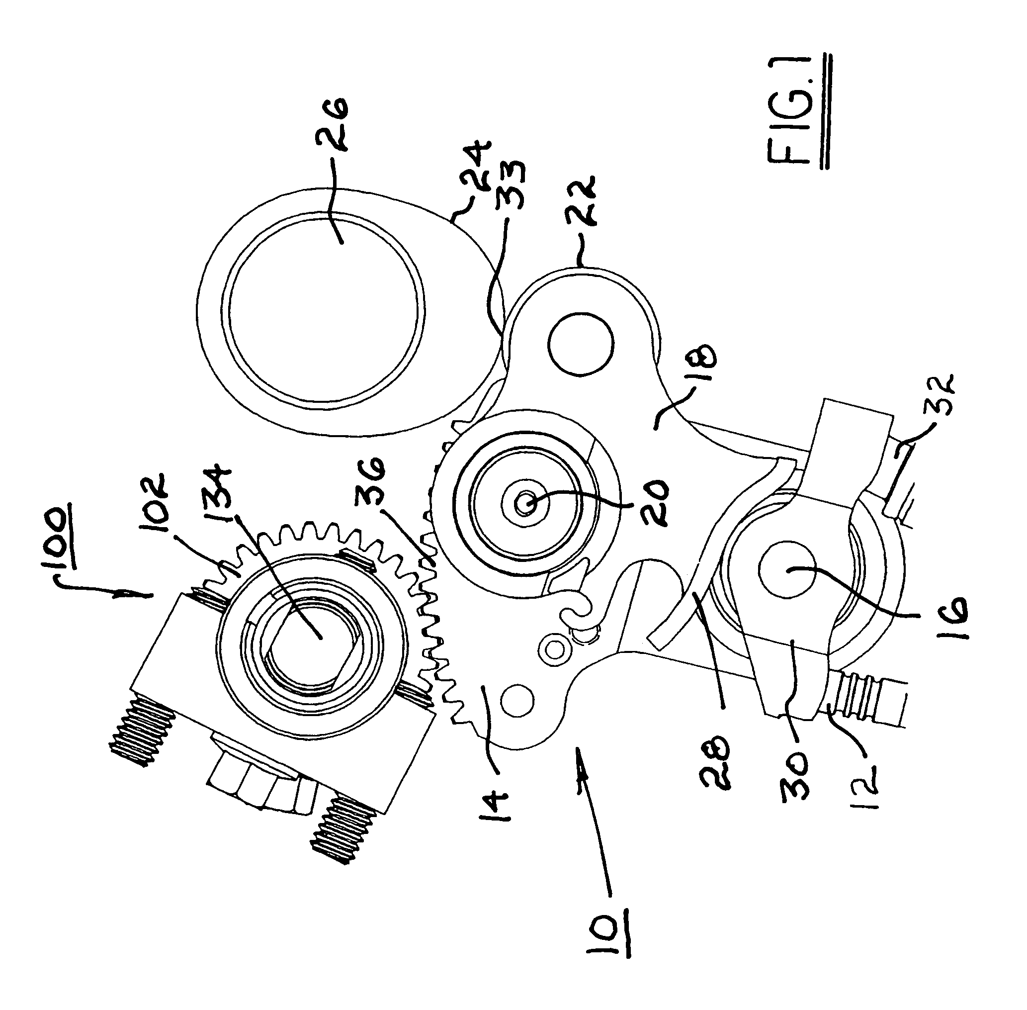
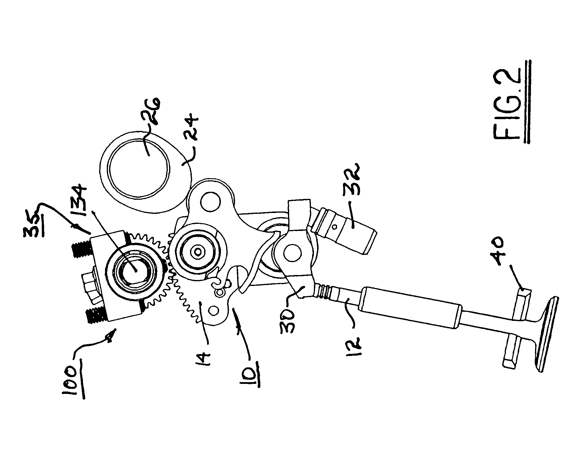
[0016]Referring to FIG. 1, a prior art CVVL mechanism 10 for an individual valve 12 is equipped with an adjustable drive gear assembly 100 in accordance with the present invention, as described in detail below.

[0017]Prior art CVVL mechanism 10 comprises a control arm 14 pivotably mounted on a control arm shaft 16; a cam follower 18 rotatably mounted on a follower shaft 20 on control arm 14, and having a roller 22 for following the surface of a cam lobe 24 disposed on a camshaft 26, and having a contoured shoe 28 for actuating a roller rocker 30 pivotable on a hydraulic lash adjuster 32 to open and close valve 12. The curved shoe 28 has a cam profile which has an extended base circle portion and a sloped portion up to full valve lift. An actuator shaft ...


PUM


Abstract

An apparatus for adjusting individual valve lift comprising a control arm assembly disposed between the cam lobes and the valve rockers for a multi-valve train. The control arm at each valve includes a driven gear. An actuator shaft includes a mating drive gear at each driven gear for rotating each control arm to vary the overall lift of the valves. In the prior art, the mating drive gears are fixed to the actuator shaft at identical fixed orientations. In accordance with the present invention, each mating drive gear is rotatably adjustable on the actuator shaft to permit changing of the orientation of each gear with respect to the actuator shaft, thereby changing the contact point of the control arm with its respective cam lobe. The lifts of the individual valves may be individually adjusted to provide equal air flow through all the valves in a multi-valve train.

Description

TECHNICAL FIELD[0001]The present invention relates to variable valve actuation for internal combustion engines; more particularly, to a Continuously Variable Valve Lift (CVVL) apparatus incorporating a rotatable control rod to vary the contact point of a cam follower with an engine cam lobe; and most particularly, to a method and apparatus for adjusting the lift of individual valves in a multi-valve train.BACKGROUND OF THE INVENTION[0002]Methods and apparatus for varying the lift of combustion valves in internal combustion engines are well known. In a typical application of such apparatus, an entire multi-valve train, for example, all the intake valves on an inline engine, undergoes simultaneous and identical actuation. Such coordinated actuation is typically accomplished by providing a variable lift mechanism for each valve, and ganging these mechanisms together via a single rotatable actuator shaft controllably driven by a motor and controller. Rotation of the actuator shaft serve...

Claims


Application Information

Patent Timeline
IPC IPC(8): F01L1/34
CPCF01L1/2405F01L13/0063F01L2820/032F01L2105/00F01L2013/0068F01L2305/00
Inventor STONE, ALBERT C.SOCHA, JOHN R.
Owner DELPHI TECH INC
Why Eureka
Try Eureka