
Slide door device for aircraft

Active Publication Date: 2010-03-11
AMERICAN HONDA MOTOR COMPANY
View PDF8 Cites 29 Cited by
  • Summary
  • Abstract
  • Description
  • Claims
  • Application Information

AI Technical Summary

Benefits of technology

[0007]An embodiment of the present invention has been made in view of the above described circumstances. An object of an embodiment of the invention is to eliminate guide rails that guide the sliding of a slide door from an outer surface of a fuselage, to thereby reduce air resistance and improve reliability.
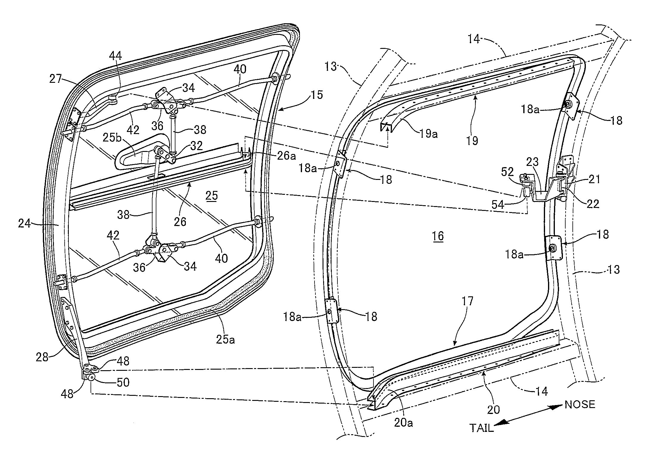
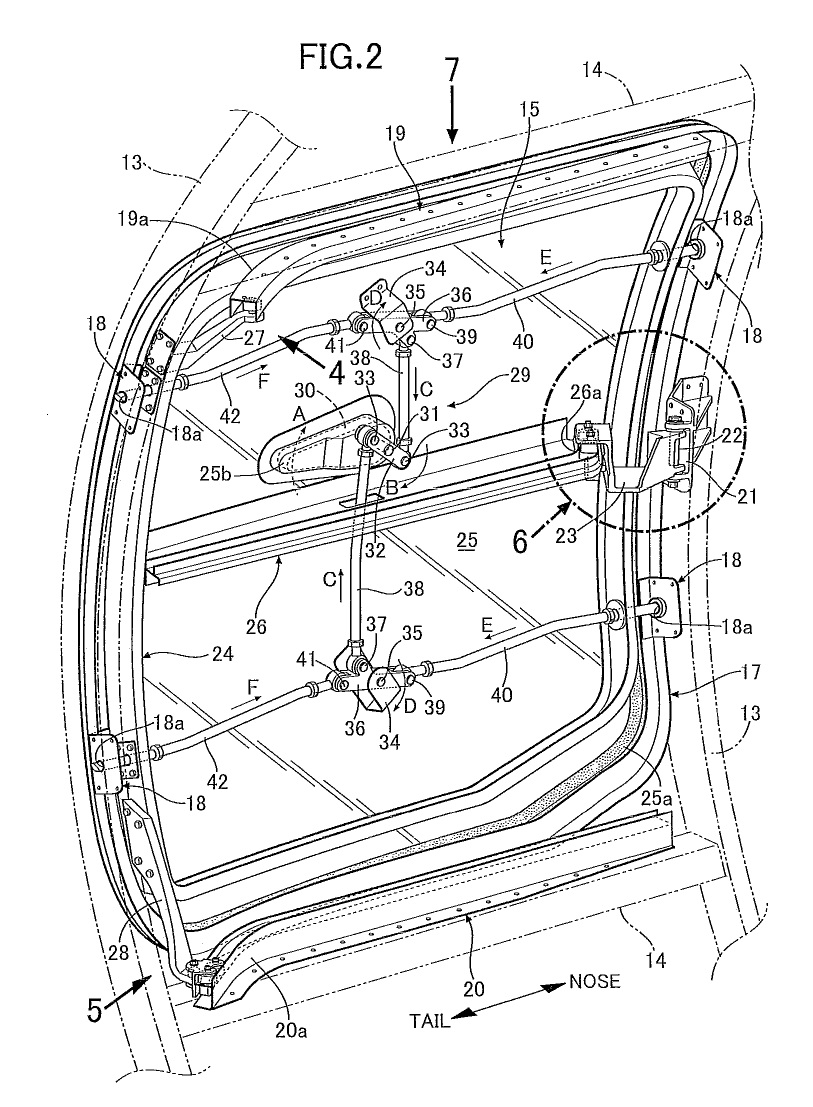
[0009]The upper guide roller at the tip end of the upper arm provided at the upper part of the slide door and the lower guide roller at the tip end of the lower arm provided at the lower part of the slide door are rollably engaged with the upper guide rail and the lower guide rail that are fixed along the upper edge and the lower edge of the door opening formed in the fuselage of an aircraft, respectively. The intermediate guide roller that is provided at the tip end of the intermediate arm provided in the door opening is rollably engaged with the intermediate guide rail that is fixed to the inner surface of the slide door. Accordingly, while smoothly guiding the slide door with the upper guide rail, the lower guide rail, and the intermediate guide rail, the intermediate guide rail is not exposed on an outer surface of a fuselage. Thus, an increase in air resistance and a decrease in reliability can be prevented.
[0011]With this configuration, one of the upper guide rail and the lower guide rail is defined as the main guide rail and another of the upper guide rail and the lower guide rail is defined as the auxiliary guide rail, and the virtual guide rail obtained by parallelly shifting the main guide rail in the up-and-down direction is defined as the virtual guide rail. The slider is pivotally supported through the spindle part at the tip end of the arm which is for the auxiliary guide rail, and the plurality of guide rollers provided in the slider are rollably engaged with the auxiliary guide rail. A shape of the auxiliary guide rail is set so that, when the plurality of guide rollers provided in the slider are rolled along the auxiliary guide rail, a movement trajectory of the spindle part of the slider matches the virtual guide rail. Accordingly, the slide door is guided by the main guide rail and the virtual guide rail that are substantially the same shape and are in a positional relationship in which they have been shifted in parallel to each other. Thus, the slide door can open and close smoothly. The shape of the auxiliary guide rail that actually guides the slider of the slide door instead of the virtual guide rail can be made a different shape to the virtual guide rail in accordance with the shape of a slider, i.e. the positional relationship between the plurality of guide rollers and the spindle part. Therefore, even in a case in which the virtual guide rail projects outwardly from the outer surface of the fuselage, the auxiliary guide rail can be disposed so as not to project outward from the outer surface of the fuselage, to thereby enable a smooth opening and closing of the slide door while preventing an increase in air resistance and a decrease in reliability.
[0013]With this configuration, the first guide roller that is rotatably supported around the vertical shaft and guides movement of the slide door, and the second guide roller that is rotatably supported around the horizontal shaft and supports the weight of the slide door are provided on at least one of the upper arm, the lower arm, and the intermediate arm. The first groove part in which the first guide roller fits and the second groove part in which the second guide roller fits are provided on the corresponding guide rail as two upper and lower tiers. Accordingly, it is possible to both guide and also support the weight of the slide door while employing a compact structure.

Problems solved by technology

However, according to the aforementioned conventional slide door device, since guide rails are provided along the outer surface of the fuselage, not only is there a problem that air resistance is increased by the guide rails, but also there is a possibility that it may not be possible to perform a smooth opening and closing of the slide door due to freezing or the like of the guide rails.

Method used


Image

  • Slide door device for aircraft
  • Slide door device for aircraft
  • Slide door device for aircraft

Examples


Embodiment Construction

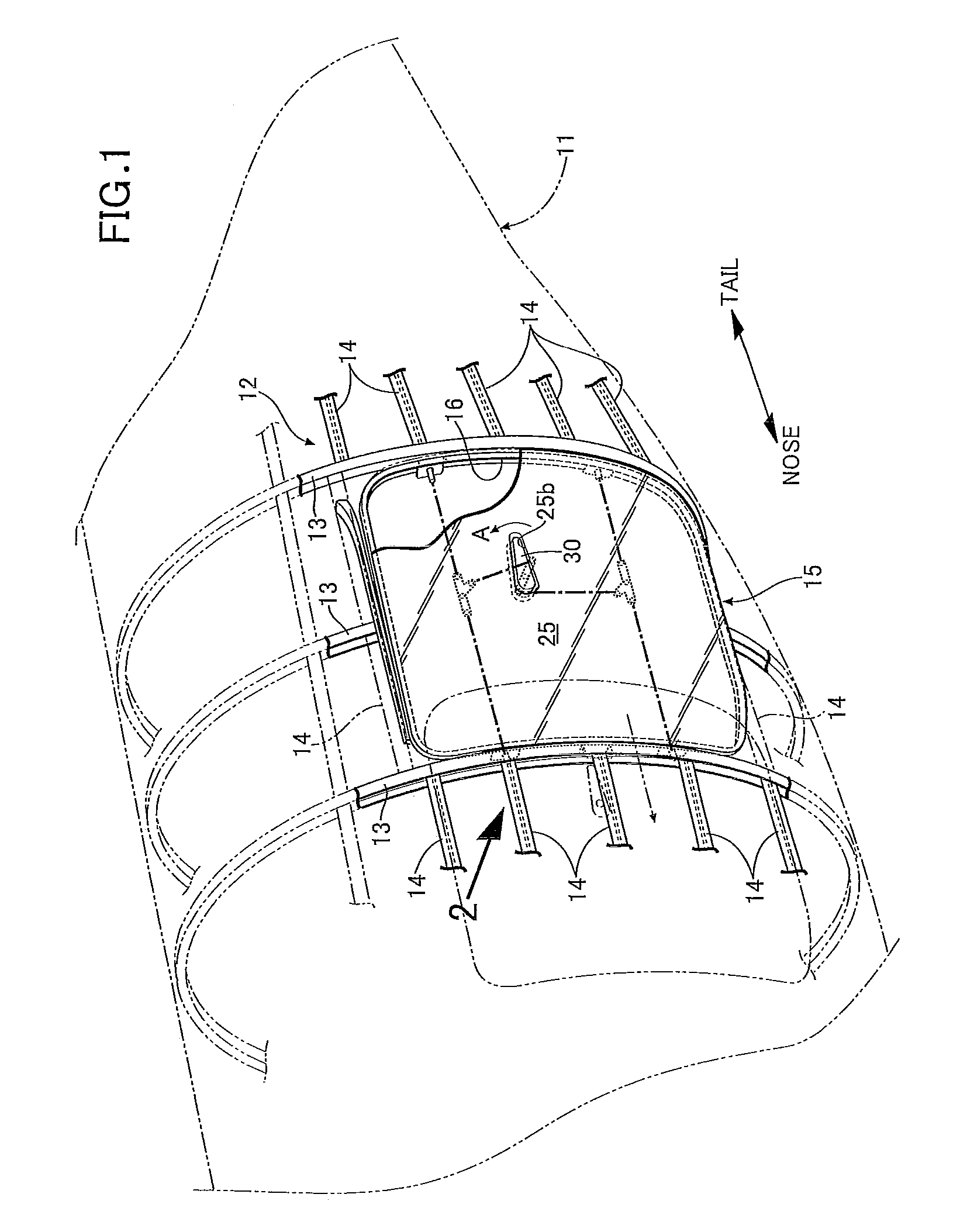
[0028]As illustrated in FIG. 1, a frame 12 of a rear fuselage 11 of an airplane is constructed by combining a plurality of ring frames 13 that form an annular shape that are disposed at predetermined intervals in the longitudinal direction with a plurality of stringers 14 that extend substantially linearly in a longitudinal direction. A door opening 16 of a slide door 15 that opens and closes an internal cargo compartment of the fuselage 11 is formed by cutting out a section of one ring frame 13 and three stringers 14 within an area that is enclosed by three of the ring frames 13 and five of the stringers 14. The plurality of ring frames 13 decrease in diameter in accordance with the closeness thereof to the tail. Accordingly, the surface shape of the fuselage 11 is not the shape of a cylindrical surface, but is the shape of a three-dimensional curved surface that is near to a conical surface.

[0029]As clearly illustrated in FIG. 2 and FIG. 3, a quadrangular door opening frame 17 wit...


PUM


Abstract

A slide door device for an aircraft includes an upper guide roller at a tip end of an upper arm provided at an upper part of a slide door and a lower guide roller at a tip end of a lower arm provided at a lower part of the slide door that are rollably engaged with an upper guide rail and a lower guide rail that are fixed along an upper edge and a lower edge of a door opening frame formed in a fuselage of an aircraft, respectively. An intermediate guide roller, provided at a tip end of an intermediate arm provided in a door opening, is rollably engaged with an intermediate guide rail that is fixed to an inner surface of the slide door, while smoothly guiding the slide door with the upper guide rail, the lower guide rail, and the intermediate guide rail.

Description

CROSS-REFERENCE TO RELATED APPLICATIONS[0001]The present application claims priority under 35 USC 119 to Japanese Patent Application No. 2008-199836 filed on Aug. 1, 2008 the entire contents of which are hereby incorporated by reference.BACKGROUND OF THE INVENTION[0002]1. Field of the Invention[0003]The present invention relates to a slide door device that opens and closes a door opening formed in a fuselage of an aircraft.[0004]2. Description of the Related Art[0005]In order to guide a slide door that opens / closes a door opening of a cargo compartment provided inside the fuselage of an aircraft, a known slide door device, as disclosed in Japanese Patent Application Laid-open No. 2005-178770, includes an upper guide rail provided along an upper edge of the door opening, a lower guide rail provided along a lower edge of the door opening with a center guide rail provided along an outer surface of the fuselage. This type of slide door device causes a slide door that protrudes to the ou...

Claims


Application Information

Patent Timeline
IPC IPC(8): B64C1/14
CPCB64C1/1438E05Y2900/502E05D2015/1055E05D15/1042
Inventor KOBAYASHI, MASAKIYAMANOUCHI, HIROSHI
Owner AMERICAN HONDA MOTOR COMPANY
Learn More