Method and System for Inductive Proximity Sensing that Includes Mounting Effect Compensation

a proximity sensor and inductive technology, applied in the field of sensing devices, can solve the problems of sensor sensitivity or accuracy degradation sensor sensitivity and sensing distance reduction,

Active Publication Date: 2010-03-11
ROCKWELL AUTOMATION TECH
View PDF22 Cites 32 Cited by
  • Summary
  • Abstract
  • Description
  • Claims
  • Application Information

AI Technical Summary

Benefits of technology

[0011]Additionally, in at least some embodiments, the present invention relates to an inductive proximity sensor capable of mounting effect compensation. The sensor includes a first coil capable of providing a first output signal representative of a first electromagnetic field component influenced by a presence or position of a target, and a second coil capable of providing a second output signal representative of a second electromagnetic field component influenced by a support structure upon which the inductive proximity sensor is mounted. The sensor also includes a processing component that is at least indirectly connected to the first coil and the second coil for receiving the first output signal and the second output signal, where the processing circuit is configured to utilize the second output signal to modify the first output signal to determine the presence or position of the target.
[0012]Further, in at least some embodiments, the present invention relates to an inductive proximity sensor with mounting effect compensation that includes a sensing portion and control circuitry. The sensing portion includes a housing including a front face, and a core positioned within and supported at least indirectly upon the housing, The sensing portion additionally includes a first coil with a central axis therethrough that is directed so as to extend through the front face toward an outer region in front of the front face within which can be positioned a target, the first coil being supported upon the core. The sensing portion also includes a second coil arranged substantially along the central axis coaxially with the first coil, the second coil having an inner diameter greater than an outer diameter of the first coil and supported at least indirectly by at least one of the core and the housing. The control circuitry is for controlling excitation of the first and second coils and receiving signals from the coils representative of electromagnetic field components experienced by the first and second coils.

Problems solved by technology

The mounting effect can result in a deterioration of the sensor's performance in terms of sensitivity or accuracy.
Unfortunately, adjusting the threshold level higher while maintaining the same measurement base value results in the sensor having a lower sensitivity and a reduced sensing distance.
However, this method is unsatisfactory, since it cannot completely eliminate the leakage magnetic field and therefore the mounting effect still exists, and also since the suppression of the mounting effect is achieved at the cost of a reduced magnetic field at the target position, such that the sensitivity and sensing distance of the sensor is reduced.
Although this method can reduce the mounting effect, it is not widely implemented because it requires a user's additional manual commissioning.

Method used


Image

  • Method and System for Inductive Proximity Sensing that Includes Mounting Effect Compensation
  • Method and System for Inductive Proximity Sensing that Includes Mounting Effect Compensation
  • Method and System for Inductive Proximity Sensing that Includes Mounting Effect Compensation

Examples


Embodiment Construction

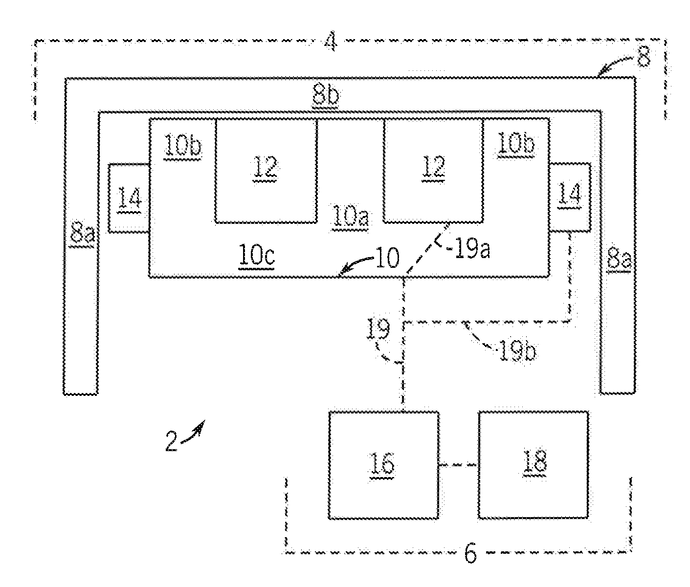
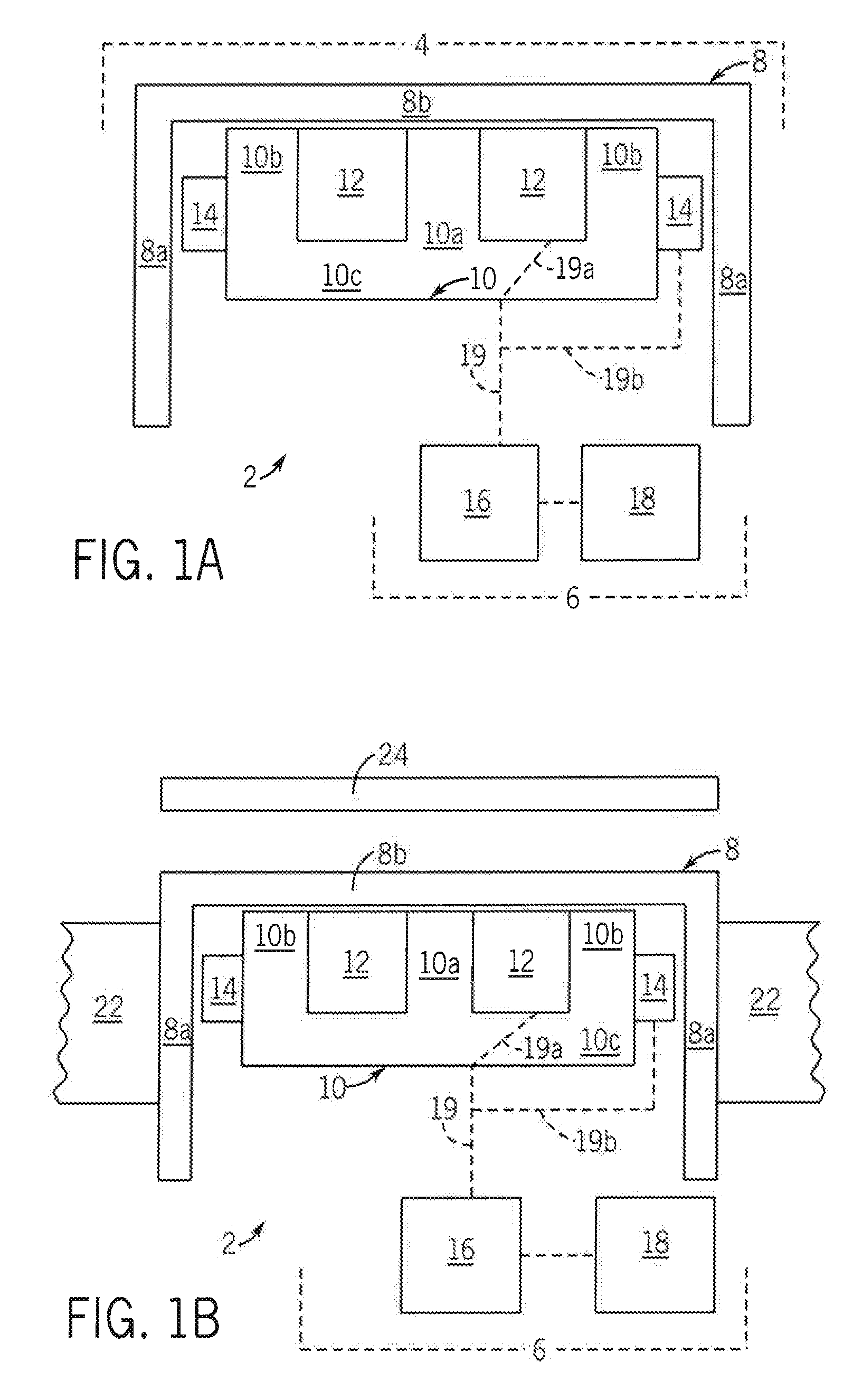
[0019]Referring to FIG. 1A, a schematic cross-sectional view of an inductive proximity sensor with mounting effect compensation system (hereinafter referred to more simply as an “inductive proximity sensor”) 2 in accordance with at least one embodiment of the present invention is shown. In the present embodiment, the inductive proximity sensor 2 is comprised of a sensing portion 4 and a processing portion 6. The sensing portion 4 includes a housing 8, a core 10, a first coil 12 and a second coil 14, each of which is substantially cylindrical (that is, rotationally symmetrical), with FIG. 1A showing a cross-sectional view taken along diameters of those components. In the present embodiment, the core 10 is comprised of a ferrite material, and includes an inner core portion 10a, an outer core portion 10b and a back portion 10c from which the core portions 10a, 10b extend forward. Both the first and second coils 12 and 14 are formed from copper wire and are mounted upon the core 10 forw...


PUM


Abstract

An inductive proximity sensor and related method for sensing a presence/position of a target, with mounting effect compensation, are disclosed. In at least one embodiment, the method includes providing a proximity sensor having first and second coils that are both at least indirectly in communication with control circuitry. The method also includes receiving respective first and second signals at least indirectly indicative of respective first and second electromagnetic field components respectively experienced by the first coil as influenced both by a target and a structure supporting the sensor and the second coil as influenced by the supporting structure. The method further includes determining by way of the circuitry a third signal based at least in part upon the first signal, as modified based at least in part upon the second signal, whereby the third signal is indicative of the presence or position of the target relative to the sensor.

Description

CROSS-REFERENCE TO RELATED APPLICATIONSSTATEMENT REGARDING FEDERALLY SPONSORED RESEARCH OR DEVELOPMENTFIELD OF THE INVENTION[0001]The present invention relates to sensing devices and, more particularly, to proximity sensors.BACKGROUND OF THE INVENTION[0002]Proximity sensors are used in various industries to detect when an object is nearby without any physical contact. A proximity sensor often emits an electromagnetic or electrostatic field, or a beam of electromagnetic radiation (infrared, for example), and looks for changes in the field or return signal. Various types of proximity sensors are available, including capacitive, magnetic and inductive. The proximity sensor is typically mounted to a base and the moving object being sensed is often referred to as the proximity sensor's target.[0003]Inductive proximity sensors that operate by creating and sensing electromagnetic fields are particularly useful for sensing the presence / position of metallic objects, such as conveyors, lift t...

Claims


Application Information

Patent Timeline
Patent Type & Authority Applications(United States)
IPC IPC(8): G01B7/00
CPCH03K17/9502H03K2217/94031H03K17/954H03K17/952
Inventor GONG, XIAOFENGQIAN, WEICHEN, WEIHUA
Owner ROCKWELL AUTOMATION TECH
Why Eureka
Try Eureka