Screen structure for field emission device backlighting unit

Inactive Publication Date: 2010-03-11
THOMSON LICENSING SA
View PDF42 Cites 18 Cited by
  • Summary
  • Abstract
  • Description
  • Claims
  • Application Information

AI Technical Summary

Problems solved by technology

While LED backlights can provide excellent

Method used


Image

  • Screen structure for field emission device backlighting unit
  • Screen structure for field emission device backlighting unit
  • Screen structure for field emission device backlighting unit

Examples


Embodiment Construction

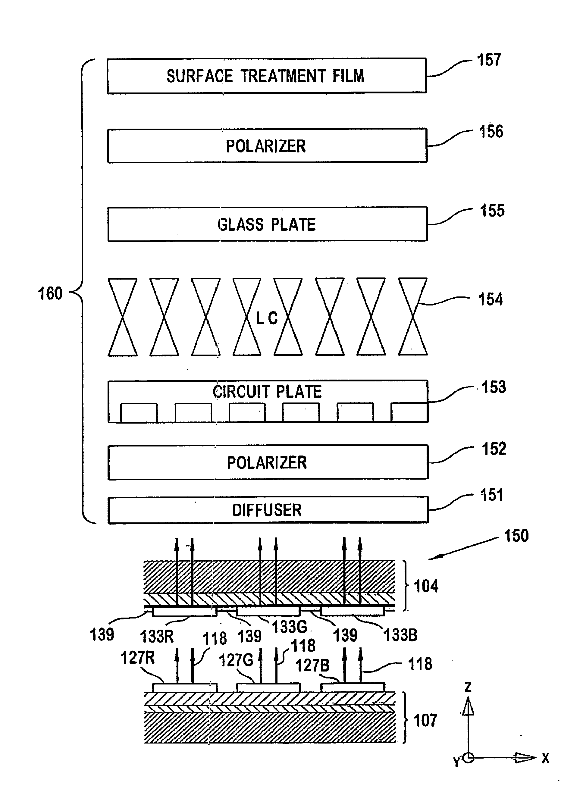
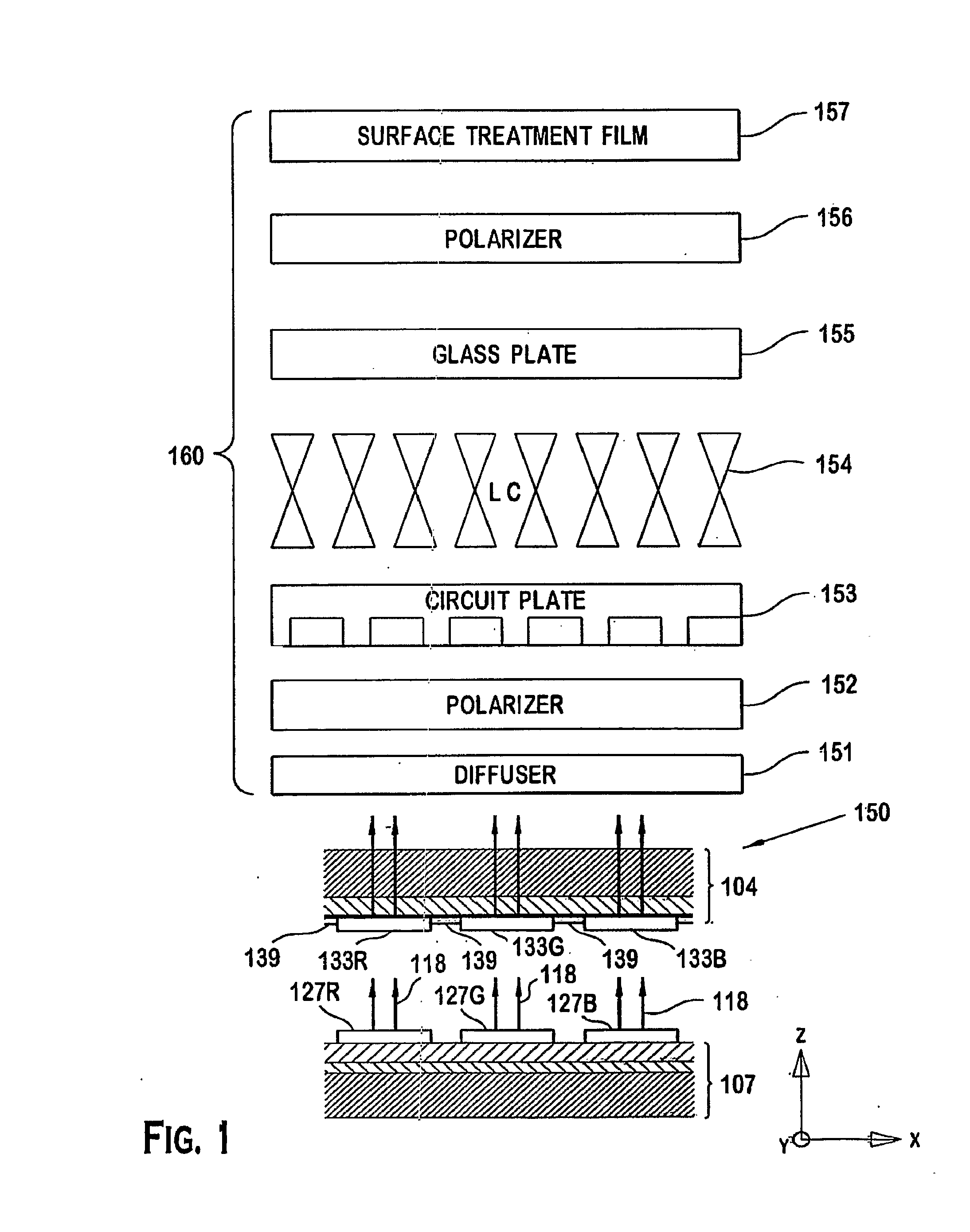
[0012]FIGS. 1-2 show an embodiment of a liquid crystal display. As shown in FIG. 1, the liquid crystal display includes a liquid crystal display front end component 160 and a field emission device backlighting unit 150. As shown in FIG. 1, the liquid crystal display front end component 160 consists of a diffuser 151, a polarizer 152, a circuit plate 153, a liquid crystal (LC) 154, a glass plate 155, a second polarizer 156 and a surface treatment film 157. Because the configuration and operation of the diffuser, the polarizer, the circuit plate, the LC, the glass plate, the second polarizer and the surface treatment film are known in the art, further description thereof will not be provided herein.

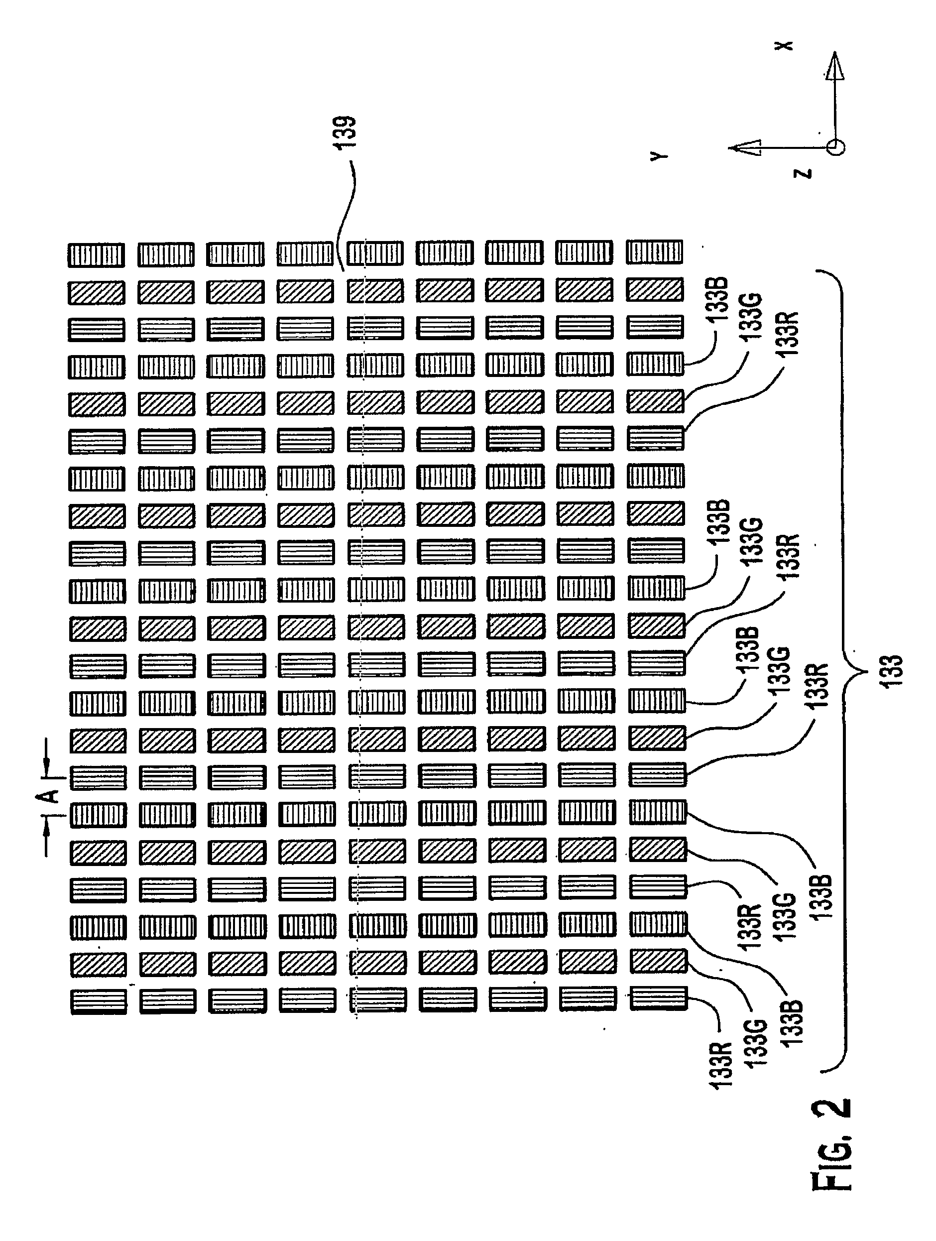
[0013]The field emission device backlighting unit 150 consists of a cathode 107 and an anode 104. The anode 104 is provided with a screen structure consisting of an arrangement of phosphor elements 133. As shown in FIG. 2, the phosphor elements 133 consist of red phosphor elements 133R, gre...


PUM


Abstract

A liquid crystal display includes a liquid crystal display front end component joined to a field emission device backlighting unit. The field emission device backlighting unit has a cathode and an anode. The cathode is provided with a plurality of emitter cells. The anode is provided with a screen structure having a plurality of phosphor elements that are each formed as a substantially continuous stripe. Each of the phosphor elements has a plurality of the emitter cells aligned therewith.

Description

FIELD OF THE INVENTION[0001]The invention relates to liquid crystal display comprising a liquid crystal display front end component and a field emission device backlighting unit. The field emission device backlighting unit includes an anode with a screen structure having phosphor elements formed as substantially continuous stripes wherein a plurality of rows of emitter cells are aligned with each of the phosphor elements.BACKGROUND OF THE INVENTION[0002]Liquid crystal displays (LCDs) are in general light valves. Thus, to create an image they must be illuminated. The elementary picture areas (pixels, sub-pixels) are created by small area, electronically addressable, light shutters. In conventional LCD displays, color is generated by white light illumination and color filtering of the individual sub-pixel light transmissions that correspond to the individual Red, Green, and Blue sub-images. More advanced LCD displays provide programmability of the backlight to allow motion blur elimin...

Claims


Application Information

Patent Timeline
IPC IPC(8): G02F1/13357G02F1/1335H01J29/06
CPCG02F1/133602G02F1/133621H01J63/06G02F2201/52H01J63/04G02F2001/133613G02F1/133613H01J31/12G02F1/1335
Inventor KLEPPINGER, JAMESMILLER, RICHARD HUGHCIAMPA, DAVID PAULRITT, PETER MICHAELDOERSCHUK, ERNEST EDWIN
Owner THOMSON LICENSING SA
Why Eureka
Try Eureka