Image forming apparatus

a technology of image forming and forming parts, which is applied in the direction of electrographic process equipment, instruments, printing, etc., can solve the problems of poor responsiveness, dramatic drop in control performance, and high cost of the driver needed to control the number of picture elements, and achieve the effect of simple configuration

Inactive Publication Date: 2010-03-11
RICOH KK
View PDF6 Cites 5 Cited by
  • Summary
  • Abstract
  • Description
  • Claims
  • Application Information

AI Technical Summary

Benefits of technology

[0015]An object of the present invention is to provide a direct recording-type image forming apparatus that is able to use a simple configuration to form a toner cloud.

Problems solved by technology

This configuration makes possible image formation without the need for an exposure optical system and electrostatic latent image, but, in principle, is not able to avoid the adherence of toner to the electrode plates of the control member, and the buildup of toner on the electrode plates gives rise to a dramatic drop in control performance.
This is problematic in that, since there is a gap of several hundred micrometers or more between the rotating roller and the control member, the control pulse applied for separation must inevitably have a high voltage of 500 V or more, and the cost of the driver needed to control the number of picture elements is extremely expensive.
Another problem is poor responsiveness and time delays associated with causing the toner adhered to the rotating roller to separate and fly.
For this reason, a strong alternating bias must be applied for separating the developer that is adhered to the developer support, causing a major reliability problem in that there is no way to avoid the separated toner flying with great force to control means side, and large amounts of developer adhering to the control means electrode.
Furthermore, this configuration cannot solve the problem of driver cost since the same gap as mentioned hereinabove exists between the developer support and control means, and the voltage value applied between the two is high (500 V or more), requiring that the control pulse for forming the field that either passes or blocks the developer to / from this field be a similarly high voltage value.
Such direct recording-type image forming apparatuses proposed in the past have numerous problems that need to be solved, such as those described above.

Method used


Image

  • Image forming apparatus
  • Image forming apparatus
  • Image forming apparatus

Examples


Embodiment Construction

(s)

[0038]Prior to explaining the present invention, the prior art of the present invention and the problems associated therewith will be explained by referring to the drawings.

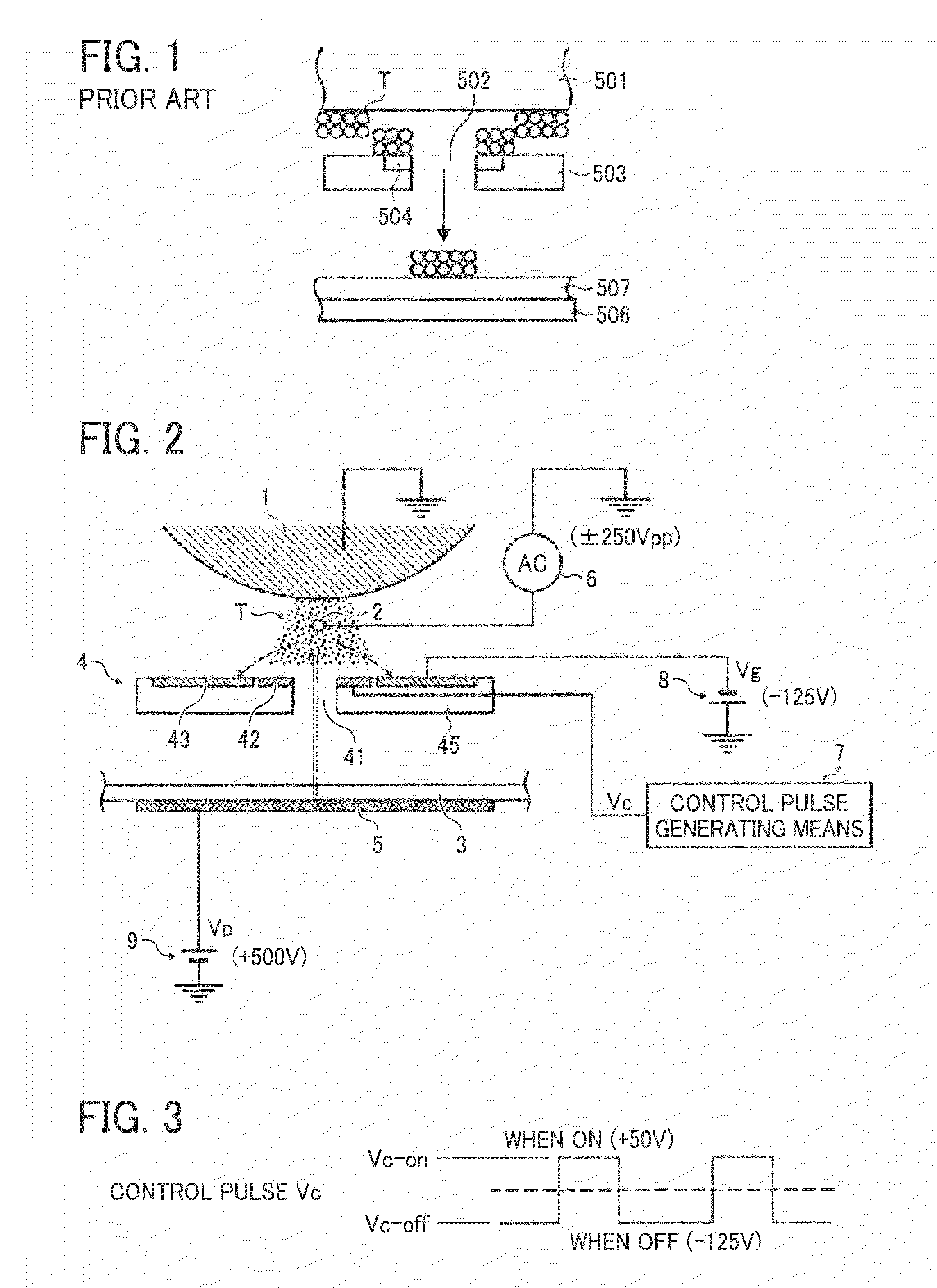
[0039]The basic configuration for forming an image using the conventional direct recording method, for example, is configured as shown in FIG. 1. In this figure, a toner carrying roller 501 is disposed as an agent carrier such that its axis extends in the left-right direction in the drawing, and carries charged toner T on its surface while being rotationally driven by driving means not shown in the drawing. A flexible printed circuit board 503 is disposed below this toner carrying roller 501 as a hole forming member for forming a plurality of holes 502. The FPC 503 comprises a plurality of flight electrodes 504 in a ring shape formed opposite the toner carrying roller 501 so as to surround the respective holes 502.

[0040]Then, down below the above-mentioned FPC 503, there are disposed a counter electrode 506 th...


PUM


Abstract

The present invention provides an image forming apparatus, which is able to prevent the adherence of toner on the surface of toner controlling means and around a toner passage hole, and to stably carry out toner passage ON/OFF control when forming an image using the direct recording method. This image forming apparatus includes: a toner carrier; recording medium means; toner controlling means, disposed between the toner carrier and recording medium means, and having a plurality of toner passage holes; and cloud electrode means disposed between the toner carrier and toner controlling means, a toner cloud being formed by applying an AC bias between the toner carrier and cloud electrode means. A control electrode and a common electrode are disposed in toner controlling means, and when the toner of the toner carrier is able to pass through the toner controlling means toward recording medium means, a loop-shaped line of electric force is formed between the recording medium means side and the toner controlling means common electrode, the loop-shaped line by-passing the control electrode.

Description

BACKGROUND OF THE INVENTION[0001]1. Field of the Invention[0002]The present invention relates to an image forming apparatus, and more particularly to an image forming apparatus that forms an image by causing a toner, which has been made to fly from a toner carrier, to adhere to recording medium means by being flown via toner passage holes, the opening and closing of which are controlled.[0003]2. Description of the Related Art[0004]An image forming apparatus of the type that directly records an image on a recording medium (comprising an intermediate recording medium) using toner (a recording material), which is called toner jet, direct toning, toner projection and the like, is known as a conventional image forming apparatus.[0005]For example, Examined Utility Model Application Publication No. H5-29479 (referred to as Prior Art 1) discloses a configuration, which has a grid electrode disposed by way of an insulating layer between a toner container and a control member comprising a pai...

Claims


Application Information

Patent Timeline
Patent Type & Authority Applications(United States)
IPC IPC(8): G03G15/06
CPCG03G15/346
Inventor HORIKE, MASANORIMATSUMOTO, FUYUHIKOSAITOH, MASANORIKONDOH, NOBUAKIKAYAHARA, SHINENDOU, OSAMUTAKAHASHI, TOMOKO
Owner RICOH KK
Why Eureka
Try Eureka