
Building structure monitoring

a technology for building structures and inspections, applied in the direction of instruments, electric digital data processing, material analysis, etc., can solve the problems of long period, inability to ascertain the timeliness of information flow, and inability to control the condition of building structures in real time or close to the real time mod

Inactive Publication Date: 2010-03-11
KOROLEV IGOR GENNADEVICH
View PDF0 Cites 8 Cited by
  • Summary
  • Abstract
  • Description
  • Claims
  • Application Information

AI Technical Summary

Benefits of technology

[0007]The main drawback of all previously used systems of building structures' monitoring is the impossibility to control the building structure condition i

Problems solved by technology

A problem, which one encounters during an inspection of a building structure, is that of getting the full, reliable, and timely obtaining data on the conditions of the structure as a whole and its separate elements.
The main shortcoming of the previously used methods of building structure monitoring is a long period, which excludes control over the condition of the structure both in real-time or close to a real period of time and does not allow ascertaining the timeliness of information flow on a critical state of the structure.
The main drawback of all previously used systems of building structures' monitoring is the impossibility to control the building structure condition in real time or close to the real time mode.
It does not allow ascertaining the receiving of information on a critical condition of the structure in due time.

Method used


Image

  • Building structure monitoring
  • Building structure monitoring
  • Building structure monitoring

Examples


Embodiment Construction

[0018]While the invention may be susceptible to embodiment in different forms, there are shown in the drawings, and will be described in detail herein, specific exemplary embodiments of the present invention, with the understanding that the present disclosure is to be considered an exemplification of the principles of the invention, and is not intended to limit the invention to that as illustrated and described herein.

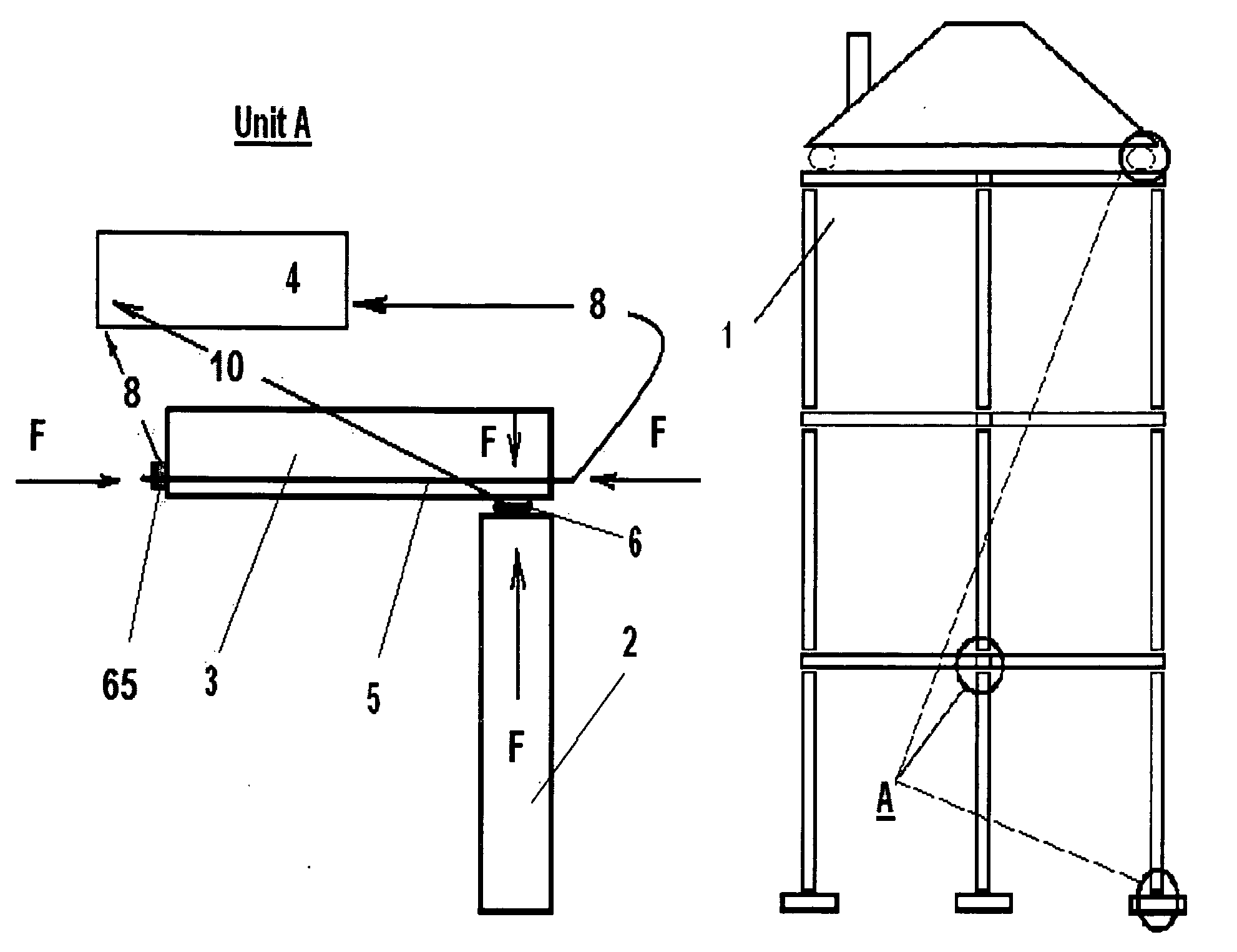
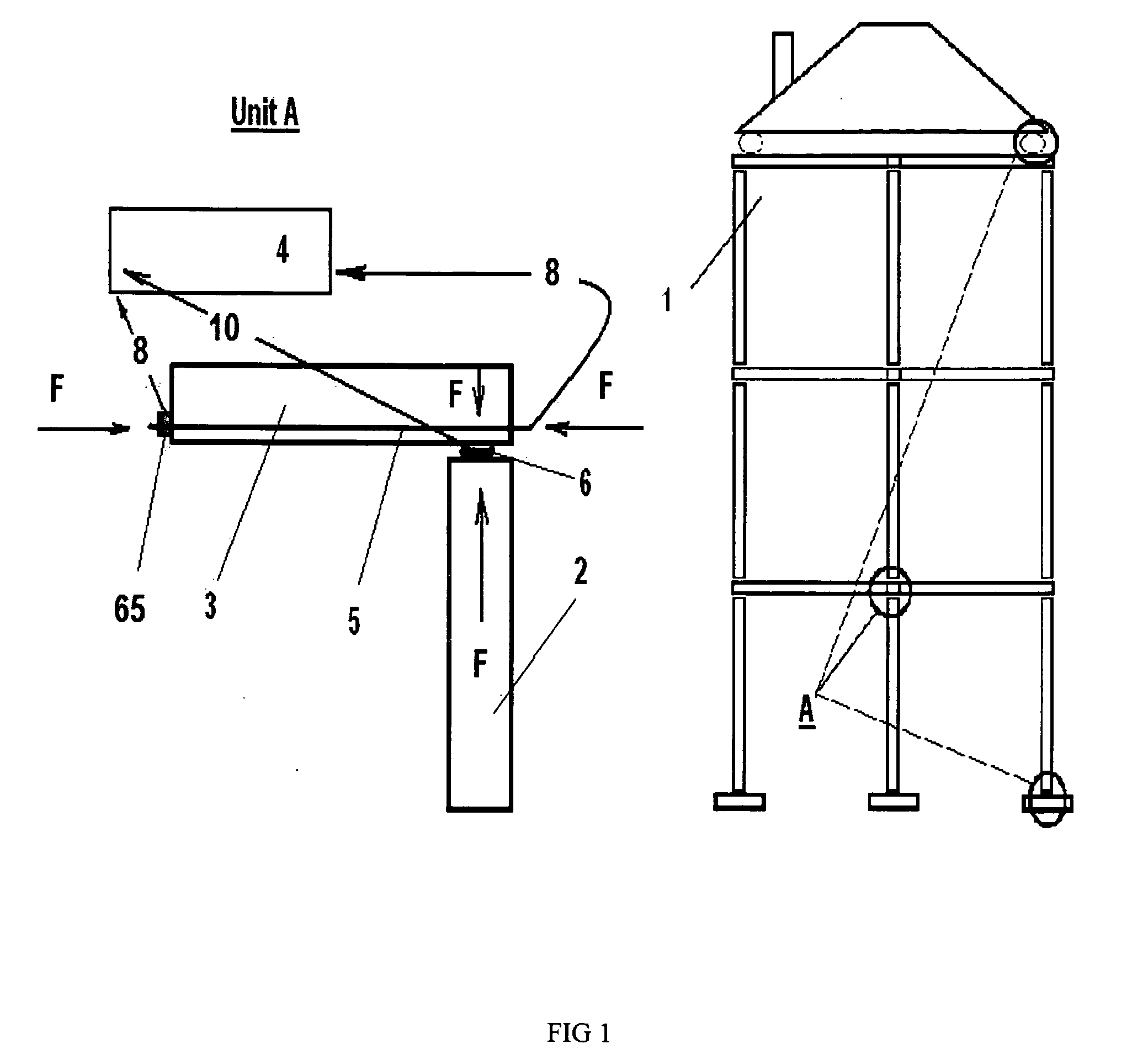
[0019]FIG. 1 illustrates the proposed method envisaging display of a building structure scheme (1), and, by the operator's choice, its separate unit A with resulting loads and their comparison with pre-calculated admissible threshold load values. The unit A exemplarily incorporates a pillar (2) and beam (3). The unit A is equipped with an autonomous device (4) controlling the carrying capacity and stability of the structure. The device 4 is connected to a reinforcement rod (5) of the beam 3, to a sensor (6) measuring compression (also known as tension-measured sensors)...


PUM


Abstract

A method for monitoring a building structure, having construction and reinforcement elements with pre-calculated threshold stretching and compression loads, comprises—determining actual stretching and compression loads developed therein based on data measured for the loads, —comparing the determined loads with the corresponding pre-calculated loads, and —displaying the determined loads and the compared results on a monitoring terminal, wherein the measured data are generated in real time or in a predetermined time mode, and obtained by measuring deviations of electric or magnetic parameters at the reinforcement elements, and by compression-measuring sensors installed between the construction elements. A system for determination of failure conditions of the building structure includes a monitoring device capable of connecting to stretching and compression loads measuring means. The device includes a terminal associated with the measuring means, capable of processing the loads data in real time or within a pre-set time interval, and displaying the data.

Description

CROSS-REFERENCE TO RELATED APPLICATIONS[0001]This application is a U.S. national phase application of a PCT application PCT / RU2007 / 000444 filed on 10 Aug. 2007, published as WO2008 / 133544, whose disclosure is incorporated herein in its entirety by reference, which PCT application claims priority of PCT / RU2007 / 000203 filed on 25 Apr. 2007.FIELD OF THE INVENTION[0002]This invention refers to the field of control (inspection) of building structures during exploitation thereof.BACKGROUND OF THE RELATED ART[0003]A problem, which one encounters during an inspection of a building structure, is that of getting the full, reliable, and timely obtaining data on the conditions of the structure as a whole and its separate elements. The problem and the ways to resolve it were described, for example, in an article entitled “Monitoring of buildings and structures” by S. V. Nikolaev et al, in Materials of the IV international Scientific-Practical Conference “Modern systems and devices of the complex...

Claims


Application Information

Patent Timeline
IPC IPC(8): G01L1/00G06F19/00
CPCG01N3/066G01N2203/0635G01N27/20
Inventor KOROLEV, IGOR GENNADEVICH
Owner KOROLEV IGOR GENNADEVICH
Learn More