Vibration generating and cooling apparatus

a technology of vibration generating and cooling apparatus, which is applied in the direction of mechanical vibration separation, piston pumps, semiconductor/solid-state device details, etc., can solve the problems of difficult mounting a mechanism to diffuse heat generated in a cabinet, difficult to efficiently convect air in the cabinet, and remarkably reduced size and thickness, so as to achieve efficient heat transfer, reduce the effect of volume and reduced siz

Inactive Publication Date: 2010-03-18
NEC CORP
View PDF0 Cites 19 Cited by
  • Summary
  • Abstract
  • Description
  • Claims
  • Application Information

AI Technical Summary

Benefits of technology

[0022]In accordance with the present invention, it is possible to provide an energy-saving vibration generating and cooling apparatus with a small volume in which a convention is caused inside and outside its cabinet by use of a mechanism to generate vibration and which efficiently transfers heat. It is hence possible to mount more efficient electronic parts while coping with the downsizing of apparatuses.

Problems solved by technology

In electronic apparatuses such as portable telephone terminals of which the size is particularly reduced, it is quite difficult to mount a mechanism to diffuse heat generated in a cabinet; even if the mechanism is mounted, it is difficult to efficiently convect air in the cabinet of which the size as well as thickness are remarkably reduced.
One of the reasons therefor will be that it is difficult to secure in the cabinet a space required to mount a fan and the like.
However, for the portable-type electronic devices for which the downsizing is underway, the space in the devices is increasingly becoming quite smaller; hence, it is likely that the motor interrupts the air flow in the arrangement.
However, it is inevitable that as for the volume in the cabinet, the volume to mount the fan is additionally required.

Method used


Image

  • Vibration generating and cooling apparatus
  • Vibration generating and cooling apparatus
  • Vibration generating and cooling apparatus

Examples


first exemplary embodiment

[0023]Description will be given of a first exemplary embodiment favorably carrying out the present invention by referring to drawings.

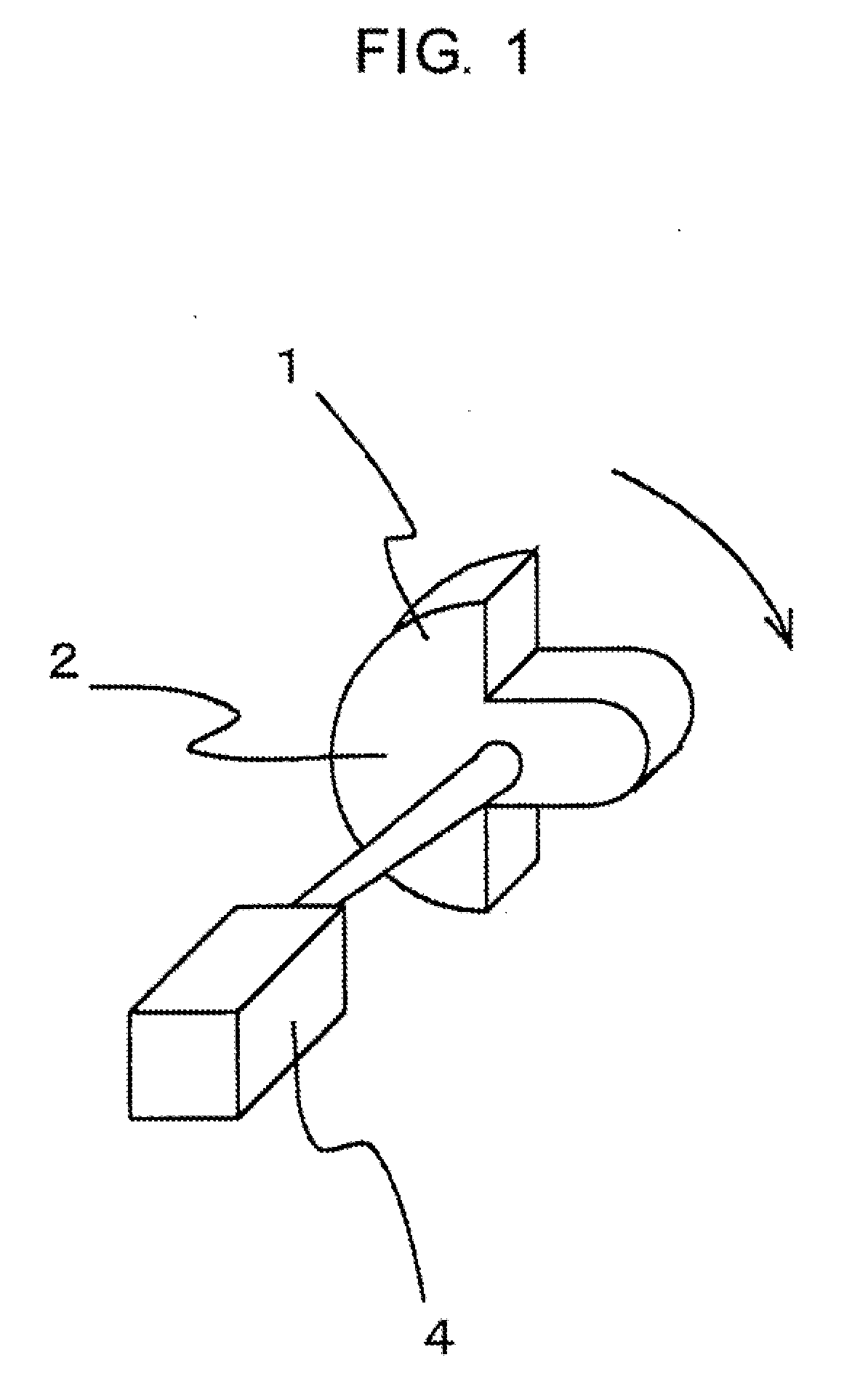
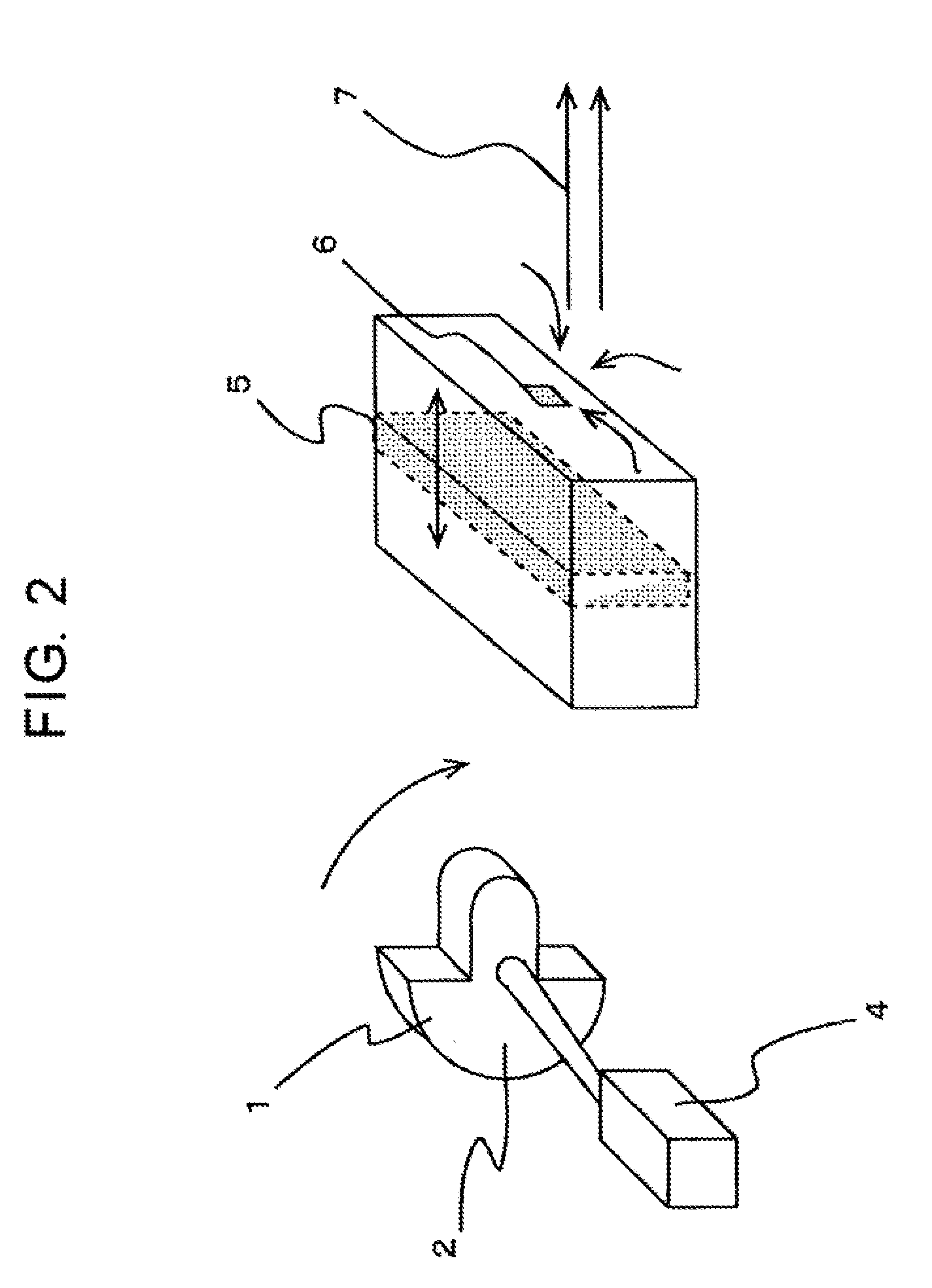
[0024]FIG. 1 is a perspective view showing a configuration of a vibration generator. This vibration generator adopts a magnet 2 as a vibrator 1. The vibrator 1 is formed in a shape of an eccentric plummet and generates vibration on the basis of the high rotation of a motor 4 and quantity of eccentricity of the plummet. Magnitude of the generated vibration expressed by the maximum acceleration of the vibrator 1 is in proportion to the weight of the plummet and distance from the vibrator 1 to the center of gravity of the plummet and is in proportion to the square of the rotary speed. Therefore, in a cooling operation, if the motor 4 is turned with a rotary speed of, for example, one fourth of an original speed, the vibration magnitude is one sixteenth of original magnitude. Moreover, when the cooling construction which functions in response to the movem...

second exemplary embodiment

[0034]Description will be given of a second exemplary embodiment which favorably embodies the present invention.

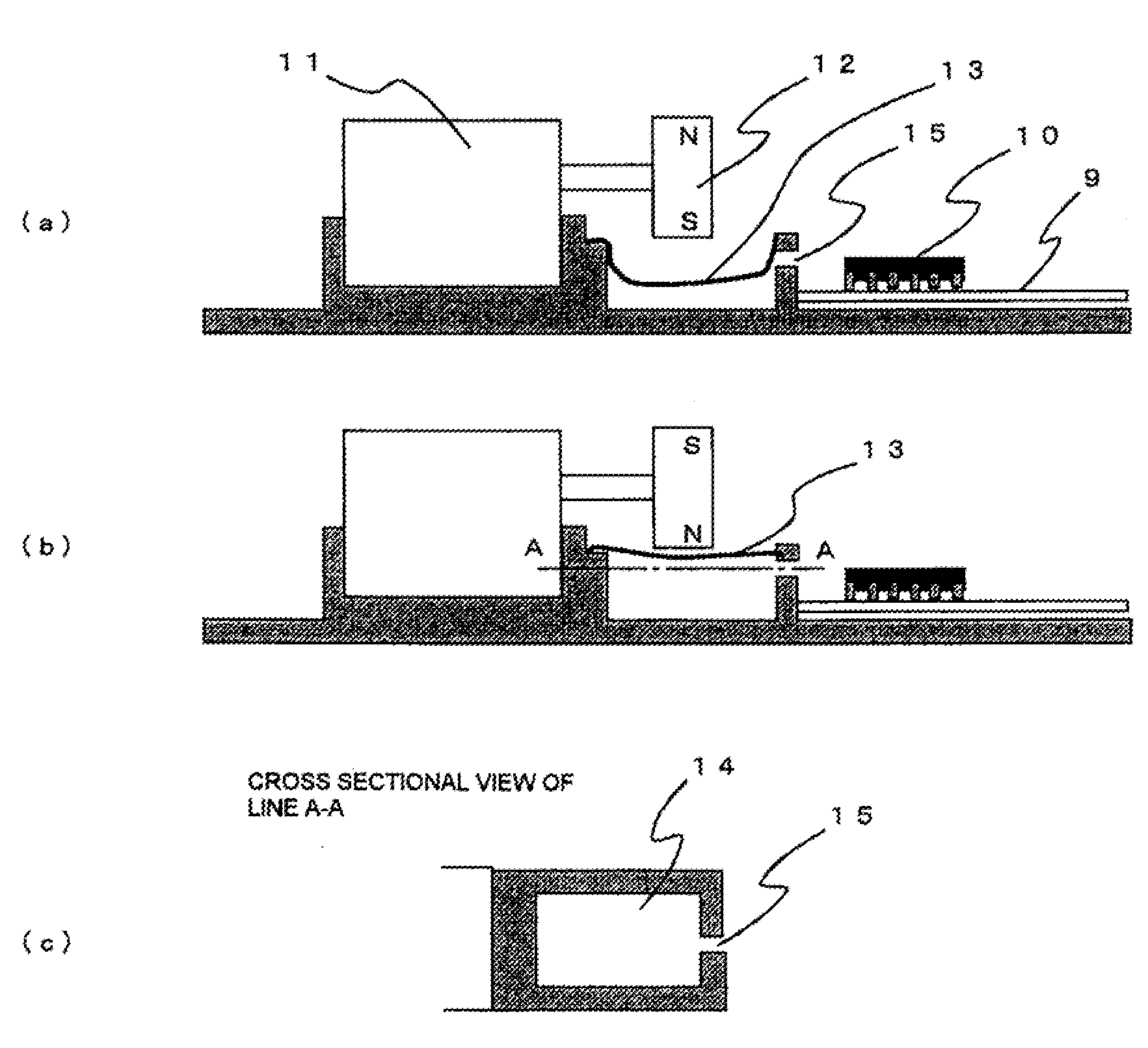
[0035]In this embodiment, the vibration unit which operates in response to the magnet vibrator is implemented by a diaphragm. In the configuration, the abrasive resistance which takes place during the operation of the piston is removed, and it is possible to simplify the construction by directly mounting the diaphragm itself on the inner wall of the cabinet. FIG. 5 shows a configuration of a cooling module in accordance with the present embodiment.

[0036]In general, a projecting section onto which a diaphragm 13 is to be attached is disposed on an inner surface of a cabinet 8 on the side of a vibrator 12 of a motor 11 held by the cabinet 8 inside the cabinet. A nozzle 15 is formed by not arranging the projecting section partially on the inner surface which faces an electronic part mounted on a printed board 9. And as FIG. 6 shows, according to the motion of the diaphragm 13...

third exemplary embodiment

[0039]Description will be given of a third exemplary embodiment which favorably embodies the present invention. FIG. 7 shows an outer appearance of a mobile telephone terminal to which a vibration generator in accordance with the present embodiment is applied. In the present embodiment, heat is efficiently dissipated through natural convection outside the cabinet.

[0040]As shown here, even for a small-sized electronic device such as a mobile telephone terminal 16, it is possible, by disposing a duct 17, to effectively collect heat on an inner wall of the duct 17. Hence, if cooling convection can be efficiently caused in the duct 17, a flow can be generated outside the cabinet by use of a magnet vibrator 1 arranged in the cabinet.

[0041]As FIG. 8 shows, when a sheet-shaped, highly-heat-conductive substance is employed as a heat dissipating section from a heat generating element 10 up to the duct 17, it is possible to transfer heat. In the cooling construction in which heat is conducted...


PUM


Abstract

There is provided an energy-saving vibration generating and cooling apparatus with a small volume in which convection is created inside and outside its cabinet and which can effectively transfer heat. It includes a motor 4, a magnetic vibrator 1 mounted onto a rotary shaft of the motor 4, and a piston 5 indicating magnetism disposed physically apart from the vibrator 1; and the piston 5 repeatedly approaches and leaves the vibrator 1 in association with rotations of the vibrator 1 such that a heat generating element is cooled by a synthetic jet 7 created by the movement of the piston 5.

Description

TECHNICAL FIELD[0001]The present invention relates to an apparatus to cool a heat generating source in equipment of electronic devices, and in particular, to a cooling apparatus which employs a vibration generator and which is mounted in an electronic device.RELATED ART[0002]With recent progress of technologies, portable electronic apparatuses are increasingly being downsized; on the other hand, both of the calorific value and calorific density tend to become greater due to developed efficiency of the apparatuses and high-density mounting of electronic parts.[0003]In electronic apparatuses such as portable telephone terminals of which the size is particularly reduced, it is quite difficult to mount a mechanism to diffuse heat generated in a cabinet; even if the mechanism is mounted, it is difficult to efficiently convect air in the cabinet of which the size as well as thickness are remarkably reduced.[0004]One of the reasons therefor will be that it is difficult to secure in the cab...

Claims


Application Information

Patent Timeline
Patent Type & Authority Applications(United States)
IPC IPC(8): H05K7/20F04D25/02
CPCB06B1/045F04D13/022H01L2924/0002F04D29/582F04D33/00F04F7/00H01L23/467H02K7/061H02K7/14H02K49/10H04B1/036H04M1/0202H05K7/20172H01L2924/00H02K7/06
Inventor SAKAMOTO, HITOSHIMIKUBO, KAZUYUKIHASHIGUCHI, TAKEYA
Owner NEC CORP
Why Eureka
Try Eureka