Identifying damage to a wire

a technology of damage detection and wires, applied in the direction of short-circuit testing, line-transmission details, instruments, etc., can solve problems such as short-circuits, serious problems, and detrimental conditions

Inactive Publication Date: 2010-03-18
THE BOEING CO
View PDF2 Cites 17 Cited by
  • Summary
  • Abstract
  • Description
  • Claims
  • Application Information

AI Technical Summary

Problems solved by technology

Damaged wiring can lead to detrimental conditions, such as short circuits.
When the damaged wiring is located in, for example, commercial or military aircraft, space vehicles, or nuclear power plants, the damaged wiring can lead to serious problems.
Although these conventional methods are effective to detect damage in a wire, such as short circuits using the hi-pot test or damaged insulation using the wire insulation test, the conventional tests can break or damage the wire.
Such voltage can damage a delicate wire or thin conductor.
Further, conventional approaches determine whether a wire is damaged, but fail to provide the type of damage, the location of the damage, or the amount of damage.

Method used


Image

  • Identifying damage to a wire
  • Identifying damage to a wire
  • Identifying damage to a wire

Examples


Embodiment Construction

[0024]Reference will now be made in detail to an implementation in accordance with methods, systems, and articles of manufacture consistent with the present invention as illustrated in the accompanying drawings.

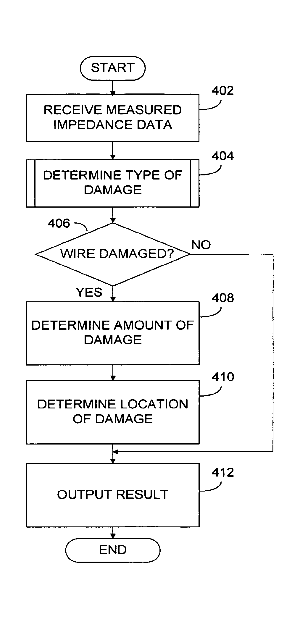
[0025]Methods, systems, and articles of manufacture consistent with the present invention determine the type of damage, the amount of damage, and / or the location of damage to a wire using broadband impedance measured from a single measurement point on the wire.

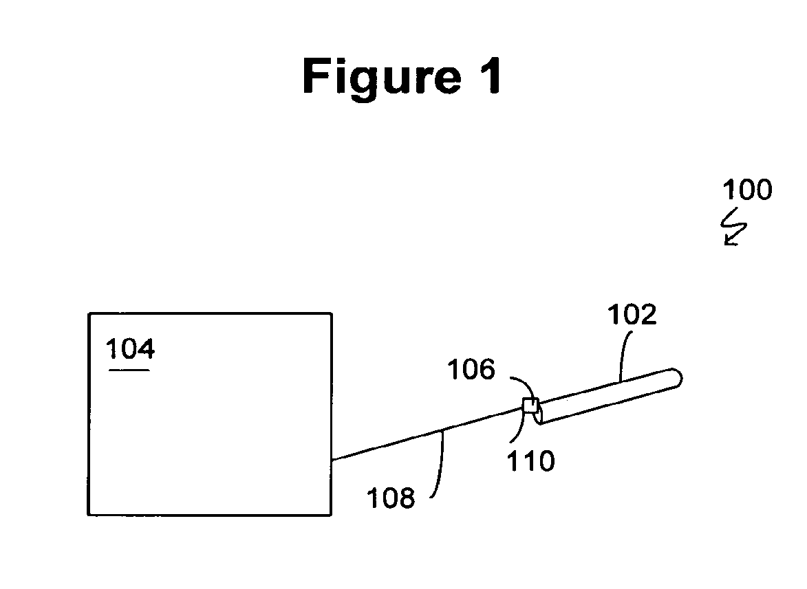
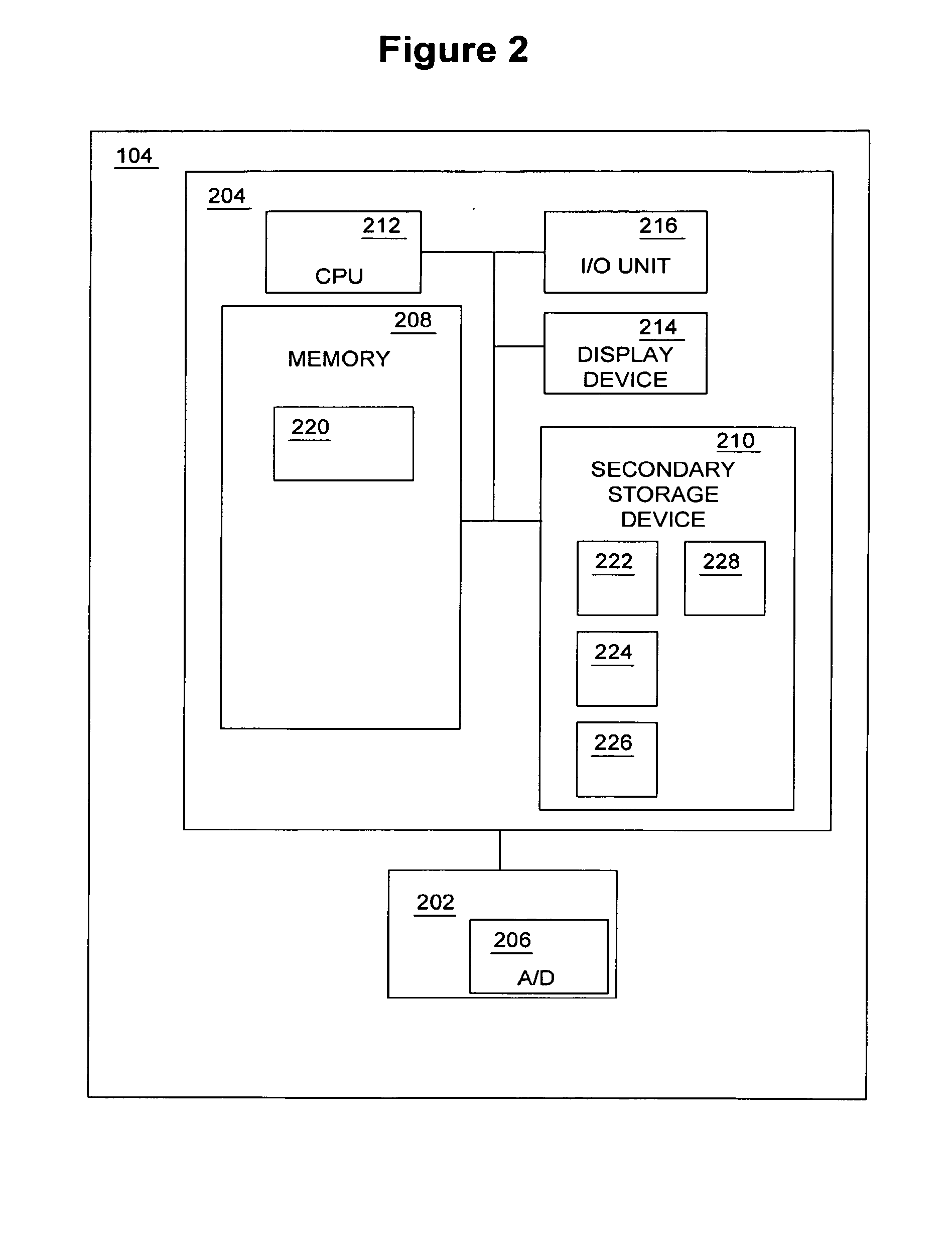
[0026]FIG. 1 depicts a block diagram of a system 100 for detecting and locating wire damage in a wire consistent with the present invention. As illustrated, the system 100 generally comprises a wire 102, which may be damaged, for example, by a short-circuit or degraded insulation. A data analysis system 104 is connected to a measurement point 106 of wire 102 via a cable 108. Cable 108 electrically connects to wire 102 via one or more connectors 110, such as a banana clip or other type of connector. Data analysis system ...


PUM


Abstract

Methods, systems, and articles of manufacture consistent with the present invention determine the type of damage to a wire, the amount of damage, and the location of the damage based on the wire's broadband impedance measured from a single measurement point. The type of damage is determined by comparing the wire's calculated dielectric function, resistance and inductance to known values that correspond to types of wire damage. The amount of damage is determined by comparing the wire's low-frequency impedance phase to known low-frequency impedance phase information that corresponds to a known amount of wire damage. The location of damage is determined by comparing the wire's high-frequency impedance phase to known high-frequency impedance phase information that corresponds to a known location of wire damage.

Description

GOVERNMENT CONTRACT[0001]This invention was made with Government support under Contract No. DTFA-03-C-00014 awarded by the FAA. The Government has certain rights in this invention.BACKGROUND OF THE INVENTION[0002]The present invention generally relates to the field of electrical wire testing and, more particularly, to methods and systems for determining the type of damage, the amount of damage, and the location of damage to a wire using broadband impedance.[0003]Damaged wiring can lead to detrimental conditions, such as short circuits. When the damaged wiring is located in, for example, commercial or military aircraft, space vehicles, or nuclear power plants, the damaged wiring can lead to serious problems.[0004]Conventional approaches for determining whether a wire is damaged include hi-pot and wire insulation tests. Although these conventional methods are effective to detect damage in a wire, such as short circuits using the hi-pot test or damaged insulation using the wire insulat...

Claims


Application Information

Patent Timeline
Patent Type & Authority Applications(United States)
IPC IPC(8): G01R31/08G01R31/58
CPCG01R31/025H04B5/00G01R31/088G01R31/52G01R31/58
Inventor ROGOVIN, DANIEL N.KENDIG, MARTIN W.
Owner THE BOEING CO
Why Eureka
Try Eureka